52
DISASSEMBLY PROCEDURES
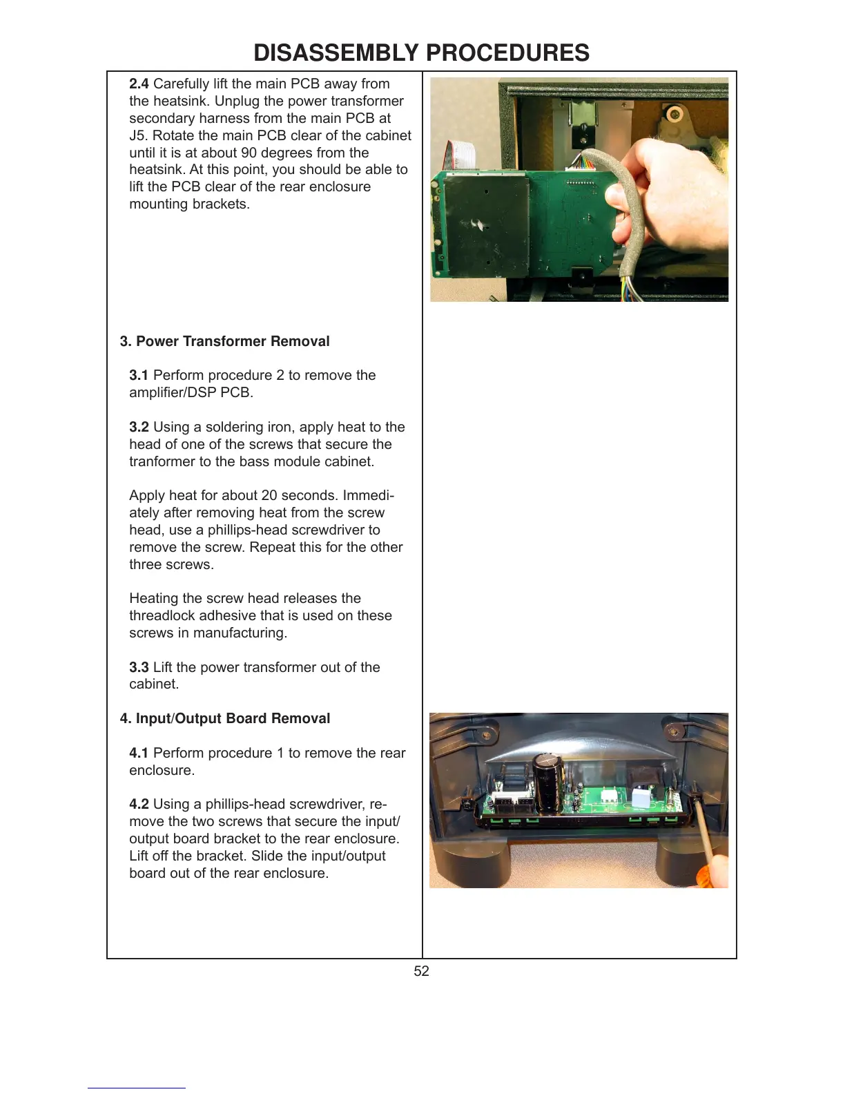
2.4 Carefully lift the main PCB away from
the heatsink. Unplug the power transformer
secondary harness from the main PCB at
J5. Rotate the main PCB clear of the cabinet
until it is at about 90 degrees from the
heatsink. At this point, you should be able to
lift the PCB clear of the rear enclosure
mounting brackets.
3. Power Transformer Removal
3.1 Perform procedure 2 to remove the
amplifier/DSP PCB.
3.2 Using a soldering iron, apply heat to the
head of one of the screws that secure the
tranformer to the bass module cabinet.
Apply heat for about 20 seconds. Immedi-
ately after removing heat from the screw
head, use a phillips-head screwdriver to
remove the screw. Repeat this for the other
three screws.
Heating the screw head releases the
threadlock adhesive that is used on these
screws in manufacturing.
3.3 Lift the power transformer out of the
cabinet.
4. Input/Output Board Removal
4.1 Perform procedure 1 to remove the rear
enclosure.
4.2 Using a phillips-head screwdriver, re-
move the two screws that secure the input/
output board bracket to the rear enclosure.
Lift off the bracket. Slide the input/output
board out of the rear enclosure.
 Loading...