EasyManua.ls Logo

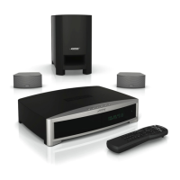
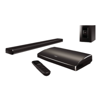
Bose 3-2-1GS Series II User Manual

Bose 3-2-1GS Series II
94 pages
To Next Page IconTo Next Page
Page #1 background imageLoading...
Page #1 background image
©2012 Bose Corporation
Reference Number 273029-SM Rev. 12
Service Manual
3
2
1, 3
2
1GS and 3
2
1GSX Series II
Home Entertainment Systems
(US and non-US Standard and Premium Versions)
Electronic Copy Only
321 Series II System
3
21GS Series II System

Questions and Answers:

Bose 3-2-1GS Series II Specifications

General IconGeneral
Audio Channels2.1
TypeHome Theater System
Number of Speakers2
SubwooferYes
Remote ControlYes
Media PlaybackDVD, CD

Summary

Safety Information

Leakage Current Test Procedures

Procedures for testing leakage current.

Insulation Resistance Test Procedures

Procedures for testing insulation resistance.

ESDS Device Handling

Main Part List - Console Assembly

Main Part List - Console Assembly (continued)

Exploded view of the 3-2-1 II console assembly.

Main Part List - GSX Console Assembly

Main Part List - GSX Console Assembly (continued)

Exploded view of the 3-2-1GSX console assembly.

Main Part List - Bass Module (Before 4/27/09)

Main Part List - Bass Module (After 4/27/09)

Electrical Part List - Console Main PCB Resistors

Console Main PCB Resistors (continued)

Final resistors for the console main PCB.

Electrical Part List - Console Main PCB Capacitors

Console Main PCB Capacitors (continued)

Final capacitors for the console main PCB.

Console Main PCB Diodes and Transistors

Console Main PCB Transistors (continued)

More transistors for the console main PCB.

Console Main PCB Integrated Circuits

Electrical Part List - Console Tuner PCB Resistors

Console Tuner PCB Resistors (continued)

Additional resistors for the console tuner PCB.

Electrical Part List - Console Tuner PCB Capacitors

Console Tuner PCB Capacitors (continued)

More capacitors for the console tuner PCB.

Console Tuner PCB Diodes, Transistors, and ICs

Electrical Part List - Bass Module DSP/Amplifier PCB Resistors

Bass Module DSP/Amplifier PCB Resistors (continued)

More resistors for the bass module DSP/Amplifier PCB.

Electrical Part List - Bass Module DSP/Amplifier PCB Capacitors

Bass Module DSP/Amplifier PCB Capacitors (continued)

Final capacitors for the bass module DSP/Amplifier PCB.

Bass Module Transistors, ICs, and Miscellaneous

Electrical Part List - Bass Module Input/Output PCB Capacitors

Disassembly Procedures - Console

Console - Outer Bezel Removal

Steps to remove the front outer bezel.

Console - Top Cover Removal

Steps to remove the console's top cover.

Console - Inner Bezel Sub-assembly Removal

Steps to remove the inner bezel with PCBs.

Console - Tuner PCB Removal

Steps to remove the tuner PCB.

Console - DVD/CD Drive Removal

Steps to remove the DVD/CD drive.

Console - Hard Disc Drive Assembly Removal

Steps to remove the hard drive assembly (GSX only).

Console - Main PCB Assembly Removal

Steps to remove the main PCB assembly.

Bass Module Disassembly Procedures

Bass Module - Rear Enclosure Removal

Steps to remove the bass module's rear enclosure.

Bass Module - Main PCB Removal

Steps to remove the bass module's main PCB.

Satellite Array Procedures

Standard Satellite Array Procedures

Disassembly for standard arrays (grille/nameplate).

Gemstone Satellite Array Procedures

Disassembly for Gemstone arrays (grille/driver).

Test Procedures - Console

Console - Analog Audio Test

Test for analog audio input/output performance.

Console - Coaxial Digital Audio Test

Test for coaxial digital audio input/output.

Console - Optical Digital Audio Test

Test for optical digital audio input/output.

Console Tuner Adjustments and Measurements

FM Adjustments

FM Stereo Separation

AM Stop Level

FM Stop Level

Hard Drive Self Test (GSX)

User Interface Tests

Bass Module Procedures

Console Test Setup Diagram

Bass Module Test Setup Diagram

Computer Setup Procedure

TAP Cable Construction

Bass Module Test Cable Construction

Console Test Cable Construction

Putting the Console into TAP Mode

Changing the Region Code

DVD Lock Options

IC Diagrams

Digital Signal Processor (DSP) IC

Console Troubleshooting Tips

Bass Module Troubleshooting Tips

Related product manuals