58
TEST PROCEDURES
13. FM Stereo Separation
13.1 Inject a 98.1 MHz (83.0 MHz Japan
units) RF signal set to 1 kHz left only modu-
lation with 10% pilot modulation and 75 kHz
total deviation at a level 58 dBuV emf into
J2001.
13.2 Reference a dB meter to the level at
the console test cable left audio output jack.
13.3 Switch the RF signal modulation to
the right channel only.
13.4 Measure the level at the left audio
output jack. It should read -25 dB or less.
Computer Assisted Tuner Test Procedures
Additional Equipment Required:
• IBM Compatible PC
• Console test cable with DC power supply
or bass module w/system cable
• ETAP test cable
• B+B Electronics RS-232 to TTL level
shifter, model 232LPTTL
Note: Refer to the computer set up instruc-
tions in the appendix for proper connection
to an IBM compatible computer.
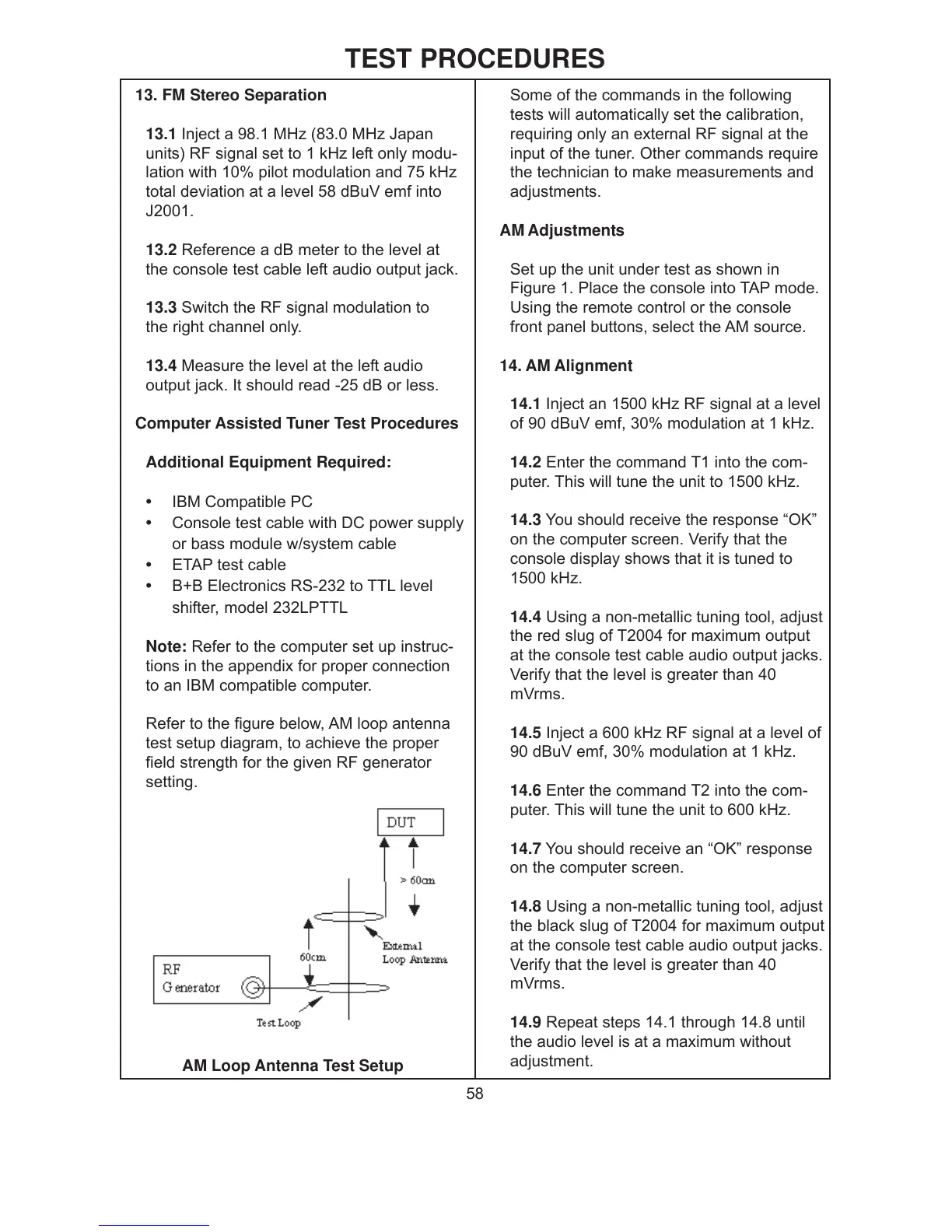
Refer to the figure below, AM loop antenna
test setup diagram, to achieve the proper
field strength for the given RF generator
setting.
Some of the commands in the following
tests will automatically set the calibration,
requiring only an external RF signal at the
input of the tuner. Other commands require
the technician to make measurements and
adjustments.
AM Adjustments
Set up the unit under test as shown in
Figure 1. Place the console into TAP mode.
Using the remote control or the console
front panel buttons, select the AM source.
14. AM Alignment
14.1 Inject an 1500 kHz RF signal at a level
of 90 dBuV emf, 30% modulation at 1 kHz.
14.2 Enter the command T1 into the com-
puter. This will tune the unit to 1500 kHz.
14.3 You should receive the response “OK”
on the computer screen. Verify that the
console display shows that it is tuned to
1500 kHz.
14.4 Using a non-metallic tuning tool, adjust
the red slug of T2004 for maximum output
at the console test cable audio output jacks.
Verify that the level is greater than 40
mVrms.
14.5 Inject a 600 kHz RF signal at a level of
90 dBuV emf, 30% modulation at 1 kHz.
14.6 Enter the command T2 into the com-
puter. This will tune the unit to 600 kHz.
14.7 You should receive an “OK” response
on the computer screen.
14.8 Using a non-metallic tuning tool, adjust
the black slug of T2004 for maximum output
at the console test cable audio output jacks.
Verify that the level is greater than 40
mVrms.
14.9 Repeat steps 14.1 through 14.8 until
the audio level is at a maximum without
adjustment.
AM Loop Antenna Test Setup
 Loading...