71
Console Test Cable Construction
Overview:
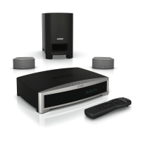
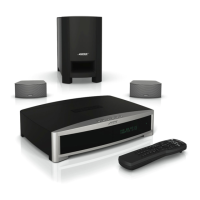
This test cable will allow you to power up and test the 321 Series II console without the system
bass module. It provides an input jack to allow connection of a Lifestyle DC power supply and
also provides left and right analog output jacks for use during testing and troubleshooting.
Parts Required:
1 - 321 Series II system cable, Bose
®
part number 269997-001
1 - Female RCA jack, red center, Radio Shack part number 274-337
1 - Female RCA jack, white center, included in Radio Shack part number 274-337
1 - Female RCA jack, yellow center
1 - Female 5.5 x 2.1 mm DC Power jack, Radio Shack part number 274-1582
1 - Lifestyle DC power supply, Model DCS91, Bose part number 256764-001
1 - AC line cord, detachable, Bose part number 258491-001. For use with 256764-001.
Procedure:
1. Cut the system cable so that you have one section about 4 feet long and another about 6 feet
long. Retain both pieces. You will use the 6 foot section to build your bass module test cable.
2. Strip back the outer cable plastic covering about 4 inches (100mm)
to gain access to the internal wires.
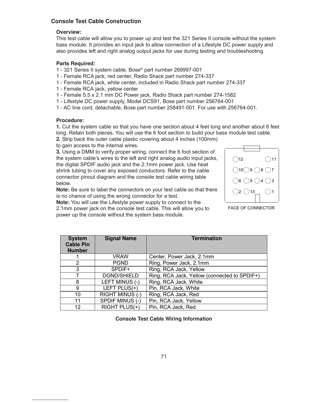
3. Using a DMM to verify proper wiring, connect the 6 foot section of
the system cable’s wires to the left and right analog audio input jacks,
the digital SPDIF audio jack and the 2.1mm power jack. Use heat
shrink tubing to cover any exposed conductors. Refer to the cable
connector pinout diagram and the console test cable wiring table
below.
Note: Be sure to label the connectors on your test cable so that there
is no chance of using the wrong connector for a test.
Note: You will use the Lifestyle power supply to connect to the
2.1mm power jack on the console test cable. This will allow you to
power up the console without the system bass module.
System
Cable Pin
Number
Signal Name Termination
1 VRAW Center, Power Jack, 2.1mm
2 PGND Ring, Power Jack, 2.1mm
3 SPDIF+ Ring, RCA Jack, Yellow
7 DGND/SHIELD Ring, RCA Jack, Yellow (connected to SPDIF+)
8 LEFT MINUS (-) Ring, RCA Jack, White
9 LEFT PLUS(+) Pin, RCA Jack, White
10 RIGHT MINUS (-) Ring, RCA Jack, Red
11 SPDIF MINUS (-) Pin, RCA Jack, Yellow
12 RIGHT PLUS(+) Pin, RCA Jack, Red
FACE OF CONNECTOR
12
3456
78910
1112
13
Console Test Cable Wiring Information
 Loading...