56
TEST PROCEDURES
7.2 Insert the ABEX TCD-721R test disc
into the console CD/DVD tray. Play the
defect tracking (scratch) track. Verify that
the disc plays properly. The nominal is a
1.6 mm defect, 1.0 mm limit.
7.3 Insert the ABEX TCD-714R test disc
into the console CD/DVD tray. Play the
defect tracking (eccentric disc) track. Verify
that the disc plays properly. The nominal is a
280 um defect, 210 um limit.
7.4 Insert the ABEX TCD-732R test disc
into the console CD/DVD tray. Play the
defect tracking (warped disc) track. Verify
that the disc plays properly. The nominal is a
1.0 mm defect, 0.7 mm limit.
7.5 Insert the Philips TS4 test disc into the
console CD/DVD tray. Play tracks 1 through
15, verifying that each track cues up within
the test limits. Nominal is 2 seconds or less,
limit 3 seconds.
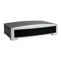
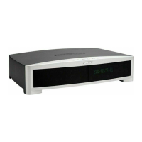
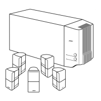
3
•2•1 Series II Console Tuner Adjustments
/ Measurements
The following tests can be performed without
the use of an IBM compatible PC.
AM Adjustments
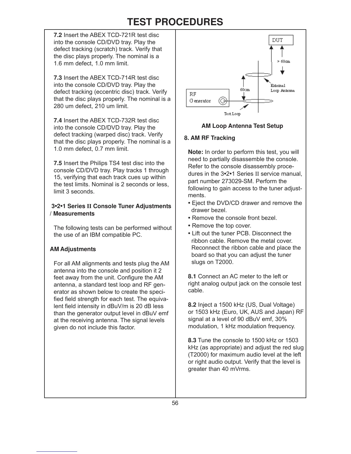
For all AM alignments and tests plug the AM
antenna into the console and position it 2
feet away from the unit. Configure the AM
antenna, a standard test loop and RF gen-
erator as shown below to create the speci-
fied field strength for each test. The equiva-
lent field intensity in dBuV/m is 20 dB less
than the generator output level in dBuV emf
at the receiving antenna. The signal levels
given do not include this factor.
8. AM RF Tracking
Note: In order to perform this test, you will
need to partially disassemble the console.
Refer to the console disassembly proce-
dures in the 3
•2•1 Series II service manual,
part number 273029-SM. Perform the
following to gain access to the tuner adjust-
ments.
• Eject the DVD/CD drawer and remove the
drawer bezel.
• Remove the console front bezel.
• Remove the top cover.
• Lift out the tuner PCB. Disconnect the
ribbon cable. Remove the metal cover.
Reconnect the ribbon cable and place the
board so that you can adjust the tuner
slugs on T2000.
8.1 Connect an AC meter to the left or
right analog output jack on the console test
cable.
8.2 Inject a 1500 kHz (US, Dual Voltage)
or 1503 kHz (Euro, UK, AUS and Japan) RF
signal at a level of 90 dBuV emf, 30%
modulation, 1 kHz modulation frequency.
8.3 Tune the console to 1500 kHz or 1503
kHz (as appropriate) and adjust the red slug
(T2000) for maximum audio level at the left
or right audio output. Verify that the level is
greater than 40 mVrms.
AM Loop Antenna Test Setup
 Loading...