19
Parameter List
Parameter Value Explanation
ACT LOW 0–126
Within the operating range of the source, this species the range that will
control the target parameter.
The target parameter will be controlled within the range specied. Normally, you
should leave ACT LOW at “0” and ACT HIGH at “127.”
ACT HIGH 0–127
WAVE RATE (*1)
0–100,
–
Species the time for one cycle of the wave pedal.
* If, due to the tempo, the time is longer than the range of allowable settings, it is then synchronized to a
period either 1/2 or 1/4 of that time.
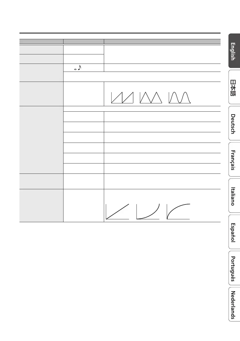
WAVE FORM (*1) SAW, TRI, SIN
Select one of the following to specify the change produced by the wave pedal.
SAW
TRI
SIN
TRIGGER
(INT PEDAL TRIGGER)
(*2)
Species how the motion of the internal pedal will be triggered.
PAT CNG
(PATCH CHANGE)
This is activated when a patch is selected.
EXP LOW
This is activated when an external expression pedal connected to the CTL 1,2/
EXP jack is set to the minimum position.
EXP MID
This is activated when the external expression pedal connected to the CTL 1,2/
EXP jack is moved through the middle position.
EXP HIGH
This is activated when the external expression pedal connected to the CTL 1,2/
EXP jack is set to the maximum position.
CTL1, 2 PDL
This is activated when an external footswitch connected to the CTL 1,2/EXP jack
is operated.
CC#1–#31
CC#64–#95
This is activated when a control change is received.
TIME
(INT PEDAL TIME)
(*2)
0–100
This species the time over which the internal pedal will move from the toe-
raised position to the toe-down position.
CURVE
(INT PEDAL CURVE)
(*2)
LINEAR,
SLOW (SLOW RISE),
FAST (FAST RISE)
Select one of the following curves to specify the change produced by the
internal pedal.
LINEAR SLOW FAST
*1: SRC=WAVE PDL only
*2: SRC=INT PDL only