Multi-DM™ User Manual Section 8 - Verifying the DM Installation
BMC Document Number: DOC-0009 Rev. 5.2 Page 25
8.1.2.1 Flat Map
All un-powered DMs, as fabricated and supplied, have a low order curvature.
The DM surface can be driven to be optically flat using a specific type of
Command Map called a Flat Map. A Flat Map can establish a flat surface
at any position within the travel of the DM actuators.
A half bias (50% deflection) Flat Map is supplied with each DM.
Loading this map will establish a planar surface with the specified surface quality
of less than 30 nm RMS at the approximate mid-point of the actuator travel.
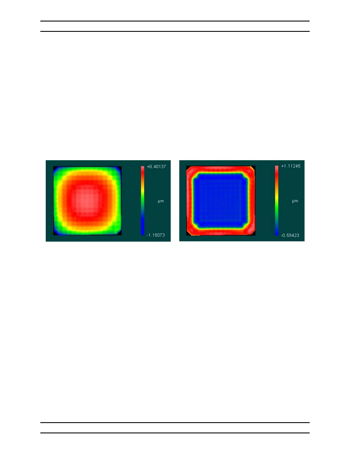
The effect of applying this Flat Map to a continuous DM is shown in Figure 6 - The
Effect of a Flat Map on a Multi-DM.
Continuous Multi-DM Surface un-powered
Segmented Multi-DM Surface is similar
Continuous Multi-DM Surface
with half bias Flat Map applied
Segmented Multi-DM Surface
is similar without sloped edge
(yellow shaded area)
Figure 6 - The Effect of a Flat Map on a Multi-DM
8.1.3 Hardware Tools
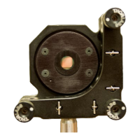
8.1.3.1 The Multi Flat Setup Mirror
The Multi Flat Setup Mirror Assembly is a form-fit compatible unit to the Multi-DM,
where the active MEMS mirror is replaced with a simple static mirror.
It can be used during setup and angular alignment to prevent shock and electrostatic
discharge (ESD) damage to the sensitive MEMS element of the Multi-DM.