Multi-DM™ User Manual Section 5 - System Components Overview
BMC Document Number: DOC-0009 Rev. 5.2 Page 11
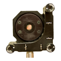
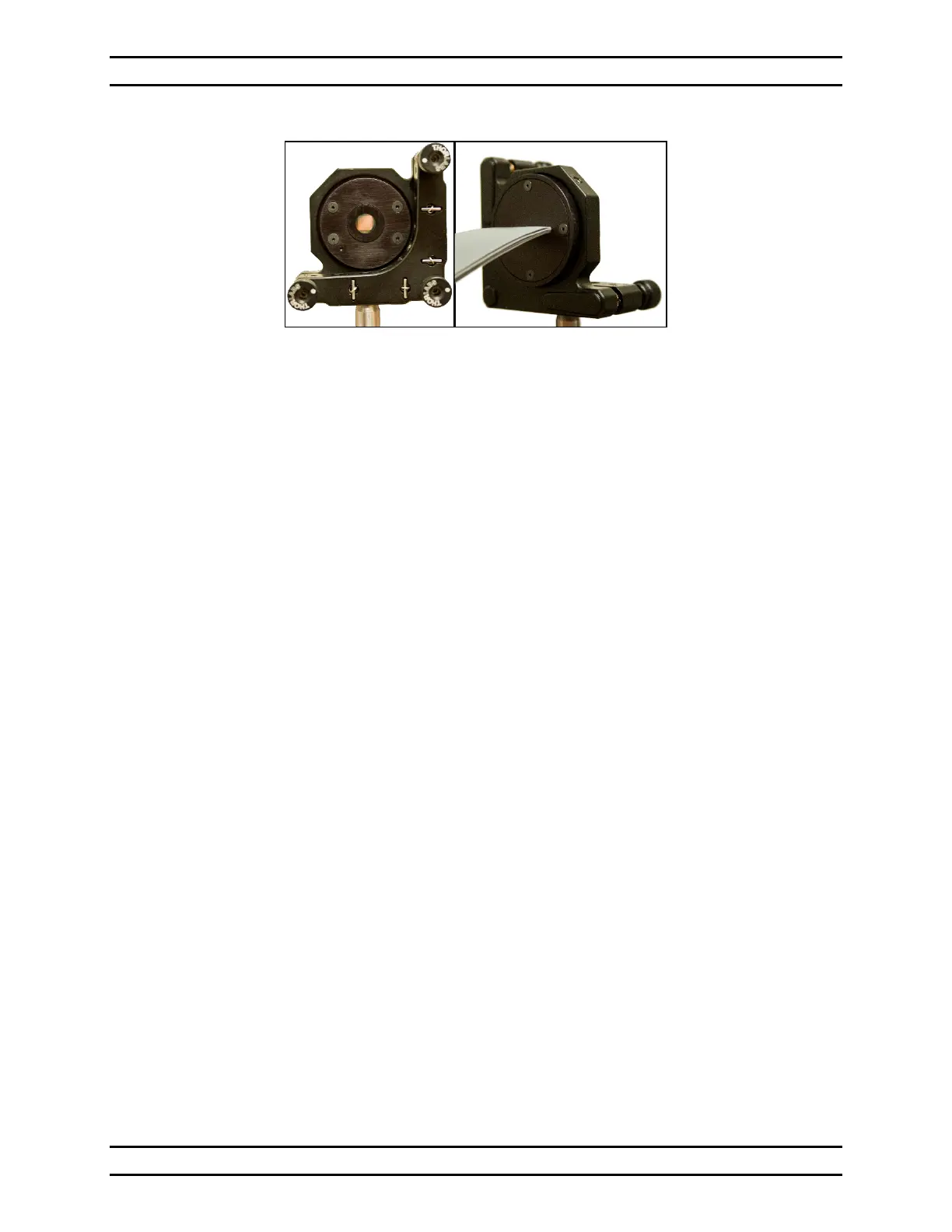
Front (Mirror) Side Rear (Cable) Side
Figure 3 - Multi-DM in Customer-Supplied Thorlabs KS2 Kinematic Mirror Mount
For installation and setup instructions of the DM enclosure see Section 7,
Hardware Installation.
5.3 Multi Driver Electronics
The Multi-DM drive electronics provide 14-bit digital control of 140 high-voltage
output channels. A host PC, connected with a USB 2.0 interface, controls each
output channel independently.
For a dimensional drawing of the Multi Driver Electronics
see Section 10.6, Multi Driver DRV00120-03 Mechanical Drawing.
For installation and setup instructions of the Multi Driver Electronics
see Section 7, Hardware Installation.
The following sections describe the connectors, displays, and controls
on the front and the rear of the unit.