Multi-DM™ User Manual Section 10 - Reference Information
BMC Document Number: DOC-0009 Rev. 5.2 Page 56
10.7 Multi Driver Auxiliary Output DE-9 Details
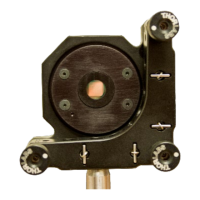
The 9-pin female connector on the Multi Driver’s front-panel
(see Figure 4 - Front Panel of Multi Driver) provides synchronization and
temperature alarm outputs, and four customizable low-voltage analog outputs.
Timing information is provided by the Frame-Sync Output on Pin 2.
When a transfer from the USB FIFO to the DACs is active (about 32µs per cycle)
the Frame-Sync Output is set high (3.3V) and when not active, i.e. between frames,
the output is set low. The minimum low time is 1µs.
The Multi Driver enclosure temperature information is provided by
the Over-Temperature Error Output on Pin 6.
When the temperature in the Multi Driver enclosure has exceeded 50° C, the Over-
Temperature Error Output is set high (3.3V) and when under that temperature the output
is set low.
Monitoring up to four actuators or program control of external devices is effected
through the four Low-Voltage Outputs on Pins 3, 4, 8, and 9.
The output on these pins can be scaled between 0 and 5V in the same way that actuator
outputs on the 37 pin J1-J4 connectors are scaled between 0 and 300V. Each pin is
addressed programmatically in the same manner as an actuator. Pin to actuator
mapping is as indicated in the table below. Utilizing these outputs requires a modified
DM profile.
To obtain this modified DM profile please contact Boston Micromachines.
The pins are numbered as shown in Figure 11 - Multi Driver Front-Panel DE-9
Connector.
The connector pinout. is provided in Table 6 - Multi Driver Front-Panel DE-9 Outputs.