Multi-DM™ User Manual Section 7 - Hardware Installation
BMC Document Number: DOC-0009 Rev. 5.2 Page 21
7. Hardware Installation
Make sure to complete the BMC SDK software installation per Section 6
BEFORE attaching the Multi Driver.
The Multi Driver hardware driver was copied to the PC by the SDK installation.
Connecting the Multi Driver before this is done will result in driver installation errors.
To install the Multi-DM hardware:
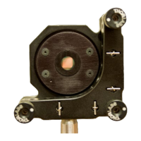
1. Mount the Multi-DM in your optical setup.
If you are using a bench top optical setup, note that compatible optical mounts
are listed in Section 5.7, Optical Mount (Optional, Customer-Supplied).
2. Position the Multi Driver such that the cables from the Multi-DM can reach the rear
panel and the cable from the PC can reach the front panel.
SHOCK HAZARD
Voltages up to 300V can be present on the Multi Driver.
Make all connections with the Driver off and the power cord disconnected.
DO NOT come into contact with the rear panel connectors when the Driver is on.
3. Plug the four Ribbon cables from the Multi-DM labeled J1 through J4
into the four DC-37 female connectors labeled J1 through J4
on the back of the Multi Driver. Match the labels on the cable connectors
to the labels on the Driver connectors.
All four cables must be attached and detected by the Multi Driver
in order to activate the high voltage power supply.
4. Connect the Multi Driver to the PC using the supplied USB cable as follows:
a) Plug the smaller end of the cable into the USB Mini B connector
on the front of the Multi Driver.
b) Plug the larger end of the cable into a USB Type A port on the PC.
5. Connect power to the Multi-Driver as follows:
a) Connect the AC power cord to the Multi Driver power transformer brick.
b) Connect the transformer brick DC power out cord to the Multi Driver.
c) Plug the AC power cord into a 100-240V wall receptacle.
The Multi Driver is supplied with a power cord with a standard NEMA 15-P plug.
Contact Boston Micromachines for cordsets for non-North American applications.