Multi-DM™ User Manual Section 10 - Reference Information
BMC Document Number: DOC-0009 Rev. 5.2 Page 49
10.4 Mirror Mapping for Multi Driver DRV00120-03
The actuator numbers on the Multi-DM are designated per Figure 9 - DM Actuator Map.
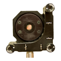
• The radial orientation of the actuator array to the DM housing is indicated by the
orientation mark on the mirror side of the housing.
Note that in some cases this may differ from the orientation shown in DMShapes.
• Actuator numbering starts at zero (0).
• The active actuator grid is surrounded by 2 rows of inactive actuator-sized
mirror elements represented by grey in the Actuator Map.
Deflecting the entire array, but not these edge rows, can provide a "raised edge",
often useful as a reference point for centering and positional calibration.
o On Continuous DMs these mirror elements are continuous
within the actuated area.
Completely surrounding actuators on the edges of the active array with
mirror surfaces tends to constrain them in a manner similar to actuators
within the array that are always surrounded by adjacent mirror surfaces.
This contributes to making these edge actuators respond more like Actuators
within the array.
o On Segmented DMs these elements are segmented
just like those within the actuated area.
• When using a continuous DM, the displacement of a single actuator at the edge of the
active actuator array should follow the Command vs. Deflection chart for a single
actuator included with the specific serialized DM.