Multi-DM™ User Manual Section 5 - System Components Overview
BMC Document Number: DOC-0009 Rev. 5.2 Page 12
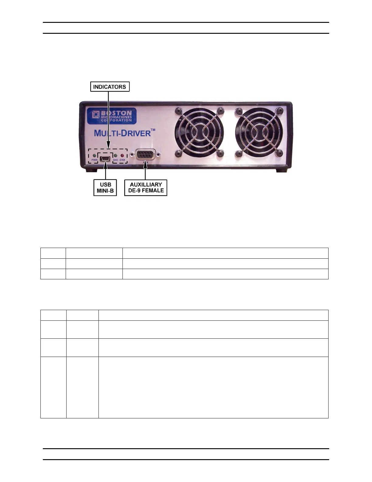
5.3.1 Multi Driver Electronics Front Panel
Figure 4 - Front Panel of Multi Driver
Table 1 - Front Panel Connections
USB 2.0 Mini-B Data connection to the control PC.
Provides timing, low voltage output, and status signals.
Table 2 - Front Panel Indicator LEDs
PWR Green When lit solid green, indicates that the power cable is plugged in
and the system is turned on.
SNC Green When lit solid green, indicates frame synchronization
and that data is being sent from the computer.
ERR Red When lit solid red, indicates a USB input buffer error.
This is usually caused and cleared by the host software.
When lit blinking red, indicates that the temperature in the Multi Driver
enclosure has exceeded 50° C and the high voltage supply in the Multi
Driver will automatically shut off.
For additional details on the ERR LED see Section 10.8, Multi Driver
Dataflow and Error Detection.