28
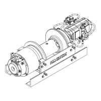
WINCH DISASSEMBLY
Refer to Drawing and Parts Key on pages 26 and 27.
1. Remove the wire rope from the winch. Drain the gear
oil from the winch by removing the drain plugs on the
bottom of the winch gearbox and winch drum. Remove
the fi ll/vent plug to speed draining.
2. Take precautions to collect hydraulic oil then remove
the hydraulic hoses connected to the winch motor.
Disconnect the extension shaft if equipped and re-
move the winch from the mounting.
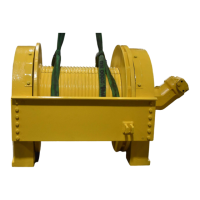
3. Set the winch on clean work bench rated for the winch
weight - approximately 650 lbs (295 kg) without acces-
sories.
4. Remove the hose connecting the winch parking brake
to the brake valve on the motor then remove the motor
from the winch (item 700) by removing the capscrews
securing the winch motor to the winch.
5. Remove the overrunning clutch assembly (100) from
the brake cylinder assembly (200). On winches with
an extension shaft, remove the solid brake coupling
rather than an overrunning clutch. Remove the drum
shaft (23) from the drum (1).
6. While supporting the brake cylinder (200). Remove
the tie plate (66) and base angles (17) from the brake
cylinder.
7. Pull the brake cylinder assembly (200) from the winch
drum. Refer to the Brake Cylinder Service section of
this manual for service information on the brake cylin-
der assembly.
8. Remove the plug (57) to access the retaining ring (12)
which holds the shifting shaft (4) in the housing and re-
move the retaining ring (12). Remove the capscrews
(42) and lockwashers (46) and pull the shifter housing
away from the ring gear.
9. Remove the thrust washer (13) from the shifter shaft
(4).
10. Remove the keeper (20) and thrust washer (53).
11. Remove the primary planet carrier assembly (300).
Refer to the Planet Carrier section of this manual for
service information on the primary planet carrier as-
sembly.
12. Remove the thrust washer (33) and then the output
planet carrier assembly (400).
13. Remove the shifter shaft (4) and shifting collar (6).
14. Remove the retaining ring (62) from the drum driver
(10), and pull the ring gear (31) from the drum driver
(10).
15. Remove the retaining ring (60) from the drum and then
remove the shaft adapter (15) from the drum.
16. If necessary, remove the ring gear (31) from the drive
end support (2) by removing the twelve capscrews
(36).
17. If necessary, remove the drum driver (10) from the
drum (1) by removing the capscrews (30).
18. Remove the spring (18) from the shaft adapter (15).
Remove the retaining ring (59) from the shaft adapter
(15) and remove the thrust washer (61) and bearing
(9).
The HP35 winch weighs approximately 650 lbs (295 kg)
without any accessories. Ensure all lifting equipment in-
cluding the overhead hoist and rigging have adequate
capacity. Use of lifting equipment that does not have ad-
equate lifting capacity or is not properly maintained may
result in property damage, personal injury, or death.
The tie plate (66) and base angles (17) hold the brake
cylinder (200) into the winch drum (1). The brake cyl-
inder may fall away from the drum when the tie plate
and base angles are removed. Failure to support the
brake cylinder when the tie plate and base angles
are removed may result in personal injury or property
damage.
CAUTION
The shifter housing (5) is retained on the ring gear
(31) by the retaining ring (12) and the capscrews
(42). Failure to remove the retaining ring (12) before
removing the shifter housing will result in damage to
internal winch shifter housing parts.
CAUTION
The winch drum (1) is retained to the drive-end sup-
port (2) by a retaining ring (62) on the drive-end drum
bearing (8). The planet carrier assemblies must be
removed from the ring gear (31) to remove the retain-
ing ring (62) and disconnect the drum from the drive-
end bearing support.
CAUTION