9
WINCH INSTALLATION
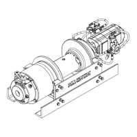
The standard HP Series winches are confi gured for bed
mount on a truck with the motor end to the passenger side
of the vehicle and the wire rope overwound on the drum.
Any other installation arrangement will require modifi ca-
tions to the winch before installation.
Headache racks or other protective structures designed
to protect the winch, truck, cab, and vehicle occupants
should be designed to enable easy access and servic-
ing of the winch. Braden recommends using a structure
designed to be easily removed should the need arise to
disassemble the winch for servicing.
1. The winch must be mounted to a fl at, rigid surface
which will not fl ex under load. The mounting surface
must be fl at within .020 in. (.05 mm) between mount-
ing fasteners. If necessary, use shim stock to ensure
proper mounting.
2. The centerline of the cable drum must be horizontal
and mounted perpendicular to the direction of pull. The
fl eet angle, or the angle created from an imaginary line
from the center of the cable drum to the load or fi rst
sheave and from this load point back to the drum bar-
rel intersection with the drum fl ange, must not exceed
1½°. Fleet angles in excess of 1½° will create uneven
spooling resulting in rapid drum or wire rope wear.
3. Grade 8, or better, fasteners are recommended for
mounting fasteners.
4. The winch base angles must be mounted securely to
the vehicle frame in a manner acceptable to the vehicle
manufacturer. Any frame adapter brackets used should
be bolted to the winch base angles as close to the gear
housing and bearing leg assemblies as possible. This
will ensure the greatest strength while minimizing dis-
tortion. Consult vehicle manufacturer before making
any modifi cations to the vehicle frame.
5. Hydraulic lines and components to operate the winch
should be of suffi cient size as to minimize the back-
pressure at the hydraulic motor work ports.
For conventional gear type motors, backpressure at full
fl ow should NOT exceed 100 PSI (690 kPa) for maxi-
mum motor shaft seal life. If high backpressures are
encountered, the motor case drain can be connected
direct to the reservoir. For backpressures in excess of
100 PSI (690 kPa), contact PACCAR Winch Division
Technical Support.
Winches equipped with Rineer vane type or piston
type motors MUST be limited to 35 PSI (240 kPa)
backpressure.
6. The winch directional control valve MUST be a three-
position, four-way valve without detents and with a
spring-centered motor spool, such that the valve re-
turns to the center (Neutral) position whenever the
handle is released, and both work ports are opened to
tank (open center, open port).
7. The hydraulic oil fi lter should have a 10 micron nominal
rating and be a full-fl ow type.
8. High quality hydraulic oil is essential for satisfactory
performance and long hydraulic system component
life.
Hydraulic oils having 150 to 300 SUS viscosity at 100°F
(38°C) and a viscosity index (VI) of 100 or greater will pro-
vide good results under normal temperature conditions.
The use of oils having a high VI will minimize cold start-
up problems and reduce the length of warm-up periods.
A high VI will also minimize changes in viscosity with cor-
responding changes in temperature.
Maximum cold weather start-up viscosity should not ex-
ceed 5000 SUS with a pour point of at least 20°F (11°C)
lower than the minimum expected temperature.
Under continuous operating conditions the temperature of
the oil at any point in the system should not exceed 180°F
(82°C). 120° to 140°F (49° to 60°C) is generally consid-
ered optimum.
In general terms; for continuous operation at ambient tem-
peratures 50° to 110°F (10° to 43°C), use SAE 20W; for
continuous operation at 10° to 90°F (-12° to 32°C), use
SAE 10W; and for applications at ambient temperatures
below 10°F (-12°C), contact the PACCAR Winch Division
Product Support Department. NOTE: The use of multi-
viscosity oils is not recommended.
9. Maximum air pressure of 130 psi for clutch and brake
air cylinders.
Flexing or uneven mounting surfaces will produce in-
ternal winch distortion which may result in rapid com-
ponent wear, overheating, poor winch performance
or an improperly engaged drum clutch which may be-
come disengaged and result in dropped loads or loss
of load control causing property damage, severe injury
or death.
DO NOT use a control valve with any detents or latch-
ing mechanism that will hold the control valve in an ac-
tuated or running position when the operator releases
the control lever. Use of the wrong type of control valve
could lead to unintentional operation of the winch, which
could result in property damage, injury or death.