44
HP35A ROTATION CHANGE
(For Winches with a Gear Motor and Overrunning Clutch)
This standard winch as shipped from the factory is confi g-
ured for installation with the motor on the passenger side
of the truck bed and the cable reeling-in over the drum as
shown below.
The two basic changes that are required to reverse the
rotation and are detailed in this procedure are:
1. The brake valve and shift block must be moved to the
opposite side of the hydraulic motor.
2. The brake clutch assembly must be set-up for the new
direction of rotation. For the HP35A this requires dis-
assembly of the brake clutch.
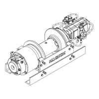
The drawing below is the standard confi guration of the
winch as shipped from the factory.
If the winch must be mounted behind the truck cab with
the motor on the driver’s side of the truck and the winch
reeling-in over the drum, the following changes must be
made for proper operation:
1. The brake valve and shift block must be moved to the
opposite side of the winch motor.
a) For the Commercial two-speed motor ONLY:
This procedure should be done by a Parker/Commer-
cial dealer so that the hydraulic motor retains its war-
ranty. The motor must be taken apart and the center
section (dotted lines) rotated 180 degrees to get the
brake valve on the opposite side. This must be done
because this two speed motor has a -16 ORB port on
the reel-out side of the hydraulic motor.
b) For the Rineer two-speed motor and Commer-
cial single speed motor, the brake valve and shift-
block must be moved to the opposite side motor split
fl ange port. The plumbing must be changed so the low-
ering signal to the brake and brake valve comes from
the opposite side as originally plumbed.
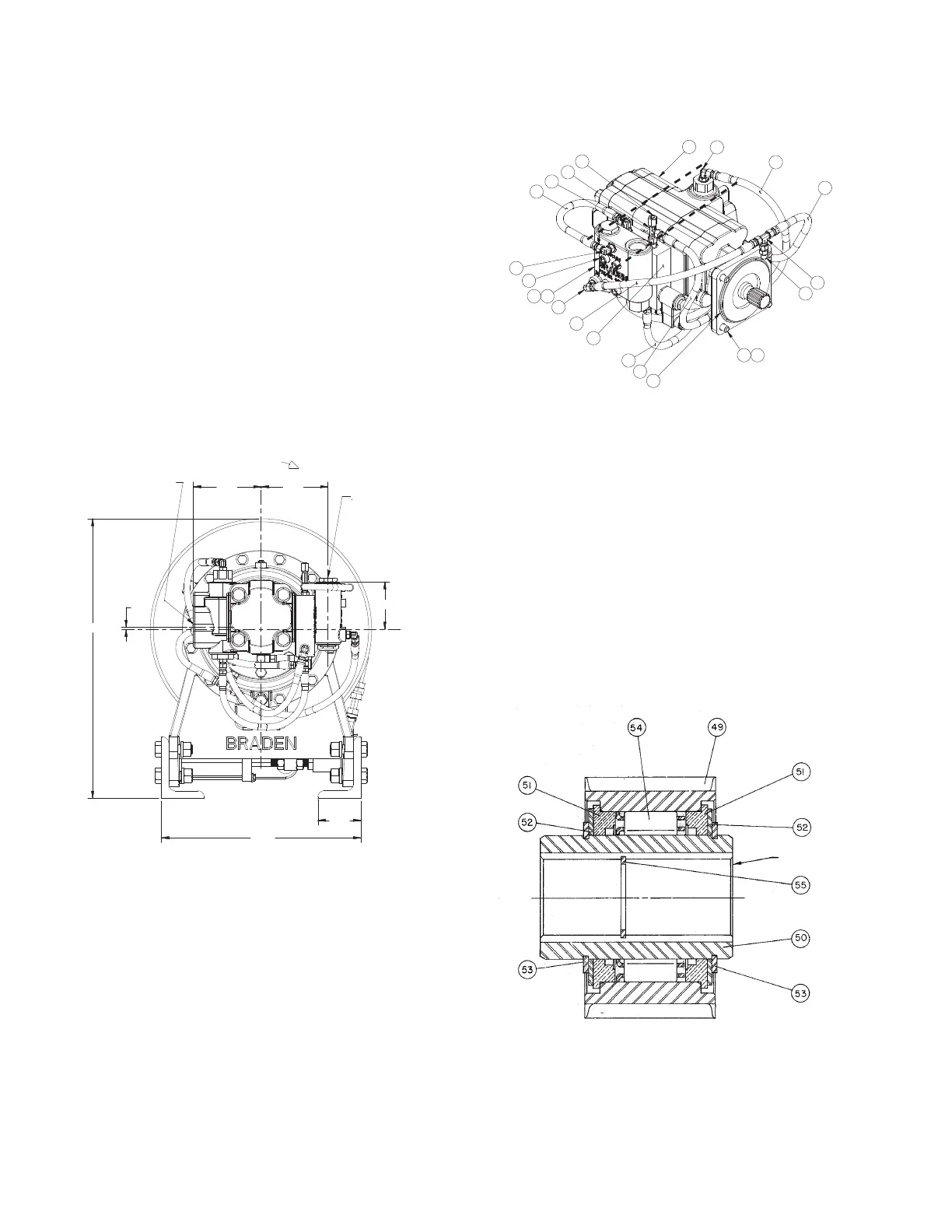
2. The brake clutch must be confi gured for counter clock-
wise rotation viewed from the hydraulic motor side of
the drum.
a) For the HP35A the brake clutch must be taken
apart and the sprag fl ipped. After reassembly, the in-
ner race should free turn in the CCW direction viewed
from the motor side.
3.50
16.25
3.87
5.445.50
REEL OUT PORT
-16 SAE ORB
1 5/16- 12 THRD
.16
22.75
REEL IN PORT
-16 SAE ORB
1 5/16- 12 THRD
REEL IN
6
11
23
8
7
9
1
15
13
9
27
21
22
12
26
17
25
9
3
2
4
9
Free rotation is changed to CCW viewed from side
“A” (motor side) when motor is mounted on driver’s
side and rope winds over drum.
HP35A SPRAG
SIDE “A”
 Loading...