8
DESCRIPTION OF OPERATION
(Winch with Solid Brake Coupling)
The HP35A winch comes in two basic confi gurations:
1. Winch has an overrunning clutch and the brake is re-
leased during reel-out only.
2. Winch has a solid brake coupling and the brake is
released during reel-in and reel-out. Generally, the
winches with a solid brake coupling will be units with
extension shafts.
The description of operation for both confi gurations is in-
cluded in this manual.
The HP35 winch consist of the following sub-groups:
1. Hydraulic Motor and Brake Valve
2. Static Brake Assembly
3. Planetary Gear Set
4. Cable Drum, Drum Shaft and Bearings
5. Drum Clutch
6. Bumper Assembly with Fairlead
7. Extension Shaft Option
The static brake assembly is a multiple disc, bathed in oil
(wet) brake pack that is spring-applied and hydraulically
released. It is equipped with a solid brake hub that couples
the motor shaft to the primary planetary sun gear. When-
ever the winch is stopped with the controls in neutral, the
static brake is applied holding the hydraulic motor shaft
fi rm and not allowing the cable drum to rotate in either
direction.
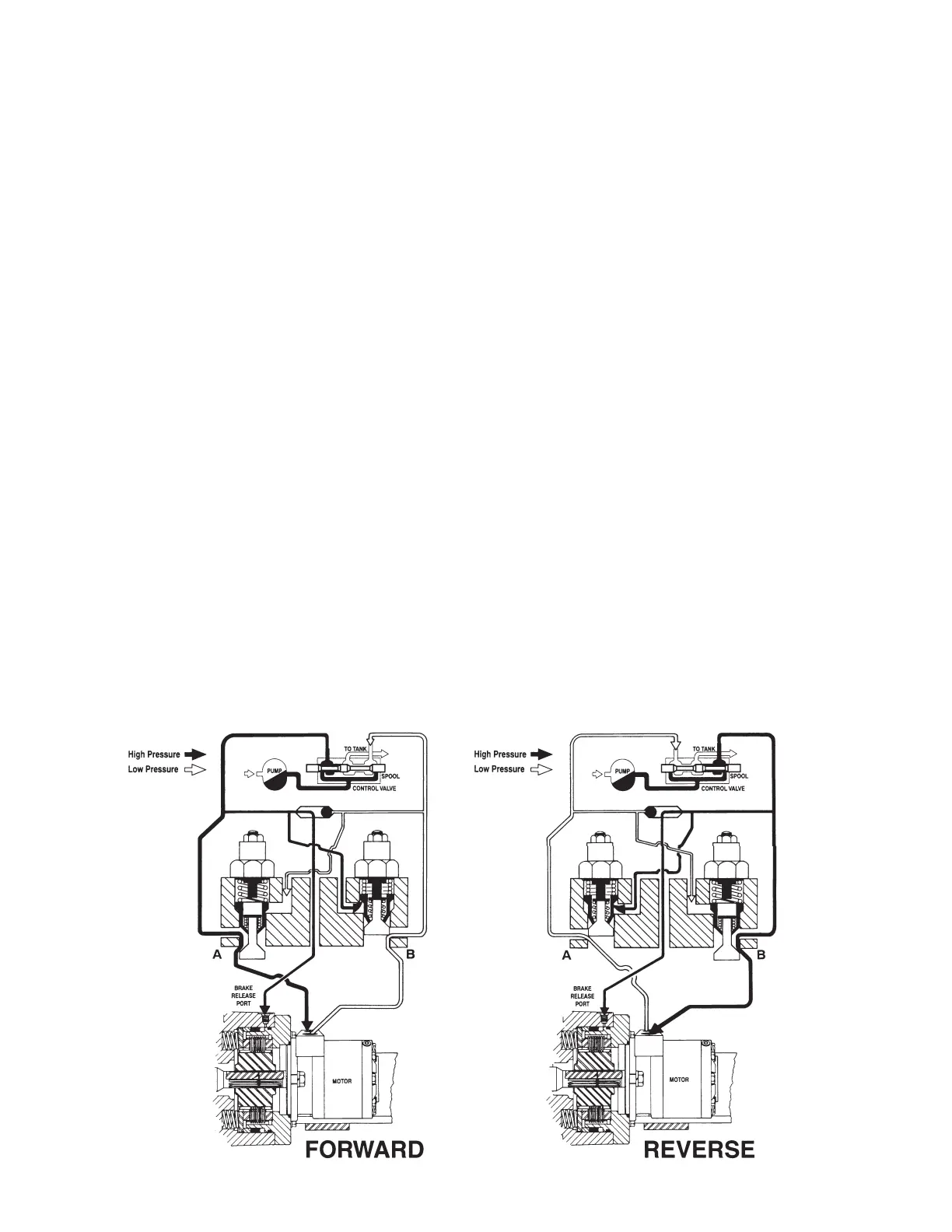
During operation, the static brake must be hydraulically re-
leased when the winch is operated in either direction. With
the control lever moved in either the REEL-IN or REEL-
OUT direction, hydraulic oil is piloted to the brake release
piston and routed to the motor at the same time. Oil fl ow
out of the motor is initially blocked by the active counter-
balance cartridge. As hydraulic oil pressure increases, the
static brake releases. At this time, oil fl ow out of the mo-
tor is still blocked. As pressure continues to increase, the
cartridge is piloted open allowing the motor shaft to ro-
tate. This sequence ensures the static brake is completely
released before any rotation occurs, resulting in minimal
wear of the friction discs.
The extent to which the cartridge opens determines the
amount of oil allowed to fl ow through it, and thus the
speed of the cable drum. Increasing the fl ow of oil to the
winch motor will cause the pressure to rise and the open-
ing in the cartridge to enlarge, allowing more oil to fl ow
and increasing the speed of the winch. Decreasing this
fl ow causes the pressure to lower, decreasing the opening
in the cartridge and slowing the speed of the winch. When
the control valve is returned to center, or neutral, and oil
fl ow is stopped, motor shaft rotation stops and the static
brake is fully applied by the force of the brake springs.