30
23. Lightly grease the bearing and seal inner races and
lower the brake cylinder assembly (200) onto the
drum.
24. Install the tie plate (72) and base angles (17) with cap-
screws (42, 47, and 65) and torque. See drawing to
identify capscrews.
25. If the winch has a solid brake coupling, ensure the re-
taining ring (63) is installed in the brake hub (62) and
install the brake hub in the brake cylinder (use a hand
pump to release the force on the brake plates to align
the plates if necessary).
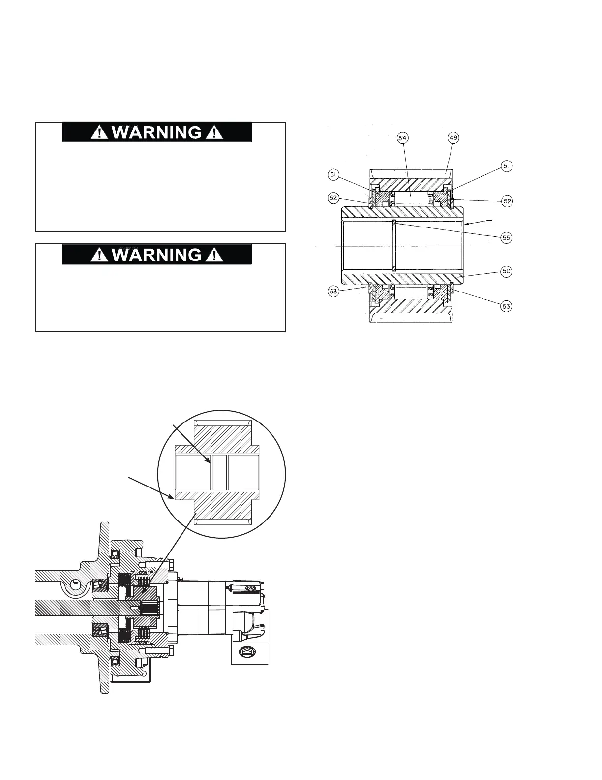
26. If the winch has an overrunning clutch, ensure it is in-
stalled with the Side “A” in the drawing below toward
the motor. For standard rotation winches the inner
race should turn freely in the clockwise direction and
lock in the counter clockwise direction while holding
the outer race.
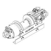
27. Install the winch motor (700) and connect the brake
release hose from the brake valve to the winch parking
brake.
The brake coupling or overrunning clutch must be in-
stalled in the winch in the correct orientation for the
winch brake to work properly. See the drawings below
for proper installation orientation. Failure to install the
brake coupling or overrunning clutch in the proper ori-
entation may result in property damage, personal injury,
or death.
The retaining ring installed in the inner race of the brake
coupling must be installed on the drum side as shown
below. Failure to install the retaining ring in the proper
groove may result in property damage, personal injury,
or death.
Retaining ring (item 63)
must be in this groove.
Nose on brake coupling
toward drum.
SIDE “A”