36
BRAKE CYLINDER PRESSURE TEST
1. Install a -4 ORB fi tting into the brake release port on
the motor adapter. Connect a hand pump with an ac-
curate 0-2,000 psi (0-13,800 kPa) gauge and shut-off
valve to this fi tting. Apply 1,000 psi (6,900 kPa) to the
brake and close the shut-off valve. Let the unit stand for
fi ve minutes. If there is any loss of pressure, the brake
cylinder should be disassembled for inspection of the
sealing surfaces, seal and O-Ring. When the source of
the pressure leak has been determined and corrected,
re-assemble the brake cylinder and repeat the test.
2. WHILE PRESSURE IS APPLIED AND THE BRAKE IS
RELEASED, install the brake coupling into the brake
pack. Turn the brake coupling back and forth to align
the splines on all the friction discs. Release the pres-
sure on the brake cylinder and remove the brake cou-
pling assembly. The brake cylinder is now complete
and ready to be installed in the winch.
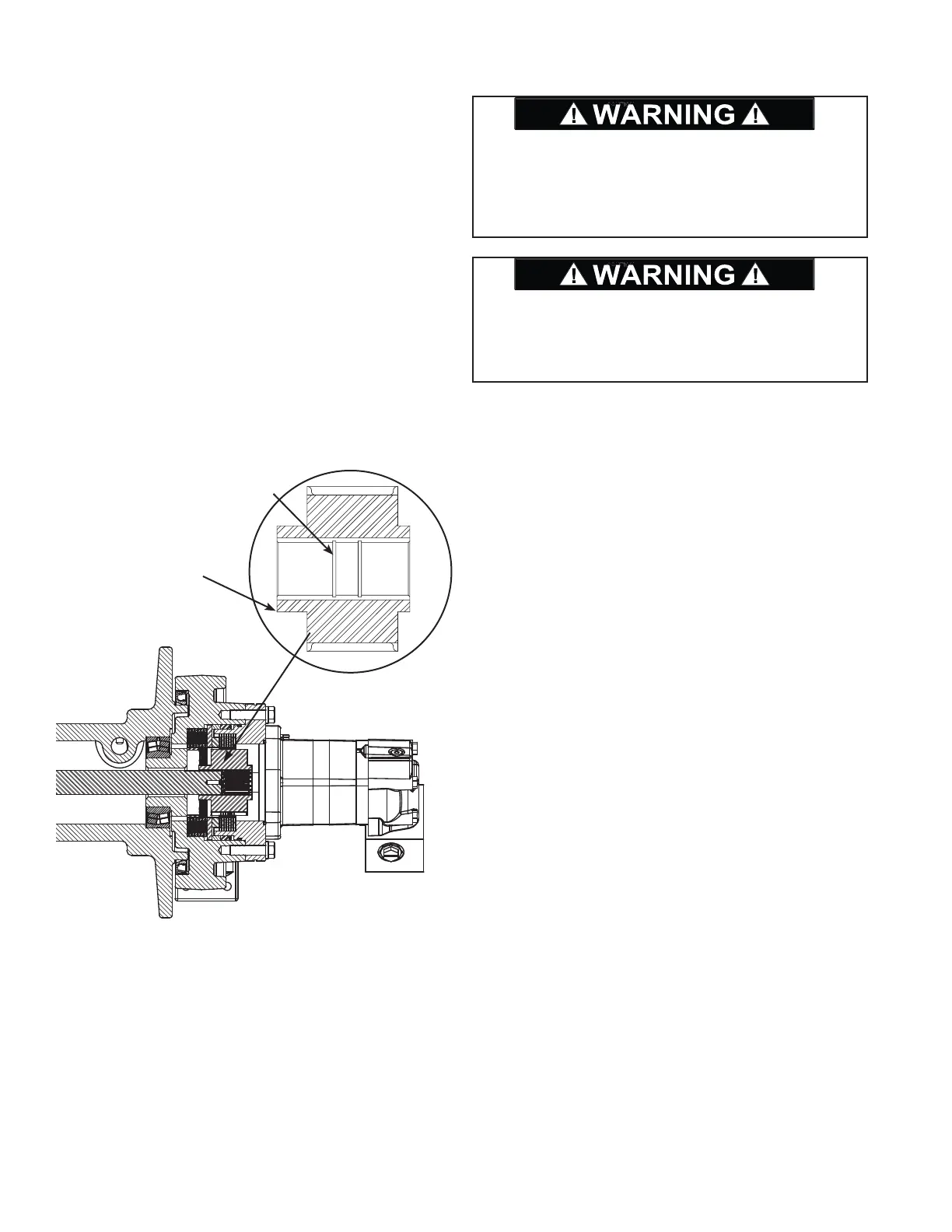
The brake coupling must be installed in the winch in the
correct orientation for the winch brake to work properly
(see drawing). Failure to install the brake coupling in
the proper orientation may result in death or personnel
injury.
The retaining ring installed in the inner race of the brake
coupling must be installed on the drum side as shown
below. Failure to install the retaining ring in the proper
groove may result in death or personnel injury.
Retaining ring (item 63)
must be in this groove.
Nose on brake coupling
toward drum.