8.1.1 Assembly
Introduction
These assembly instructions describe how to attach the following:
• Disc Joint
• Array Holder
• VarioGuide Array
How to Attach the Disc Joint and Array Holder
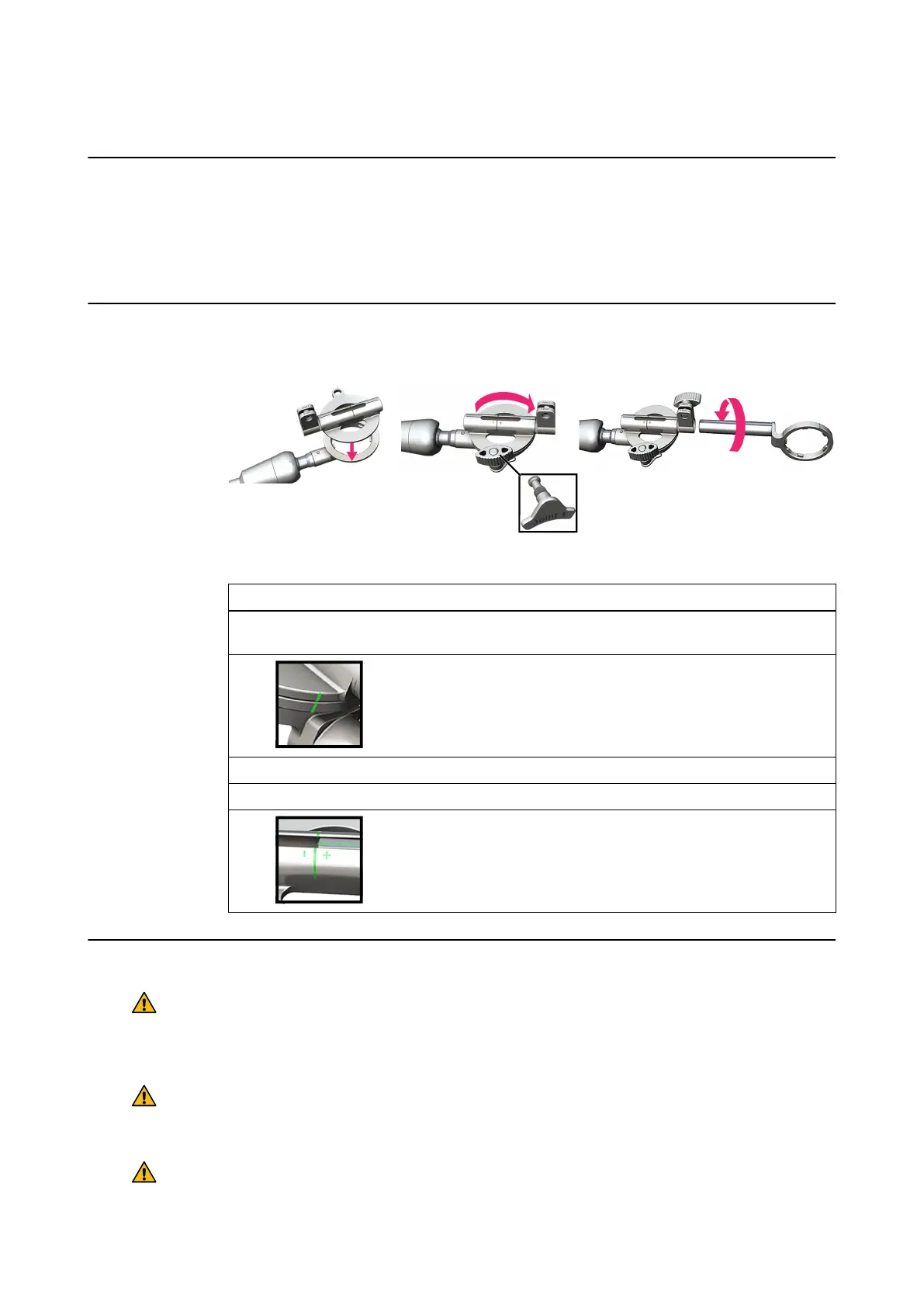
Figure 53
Step
1. Place the disc joint onto the ring of the VarioGuide arm, by fitting the six teeth on the ring
into the indentations on the disc joint ①.
2.
Rotate the disc joint 180° to the position shown ②, so that the 2 lines are
aligned. Insert the Joint 1 lock and position the lock so that it fits against
the ring of the VarioGuide arm.
3. Secure Joint 1 by tightening the screw clockwise.
4. Insert the Joint 2 lock partway into the disc joint.
5.
Screw the array holder into the disc joint ③ until the lines on both compo-
nents are aligned, securing it by tightening the Joint 2 screw.
General Safety Considerations
Warning
Never loosen the joints while an instrument is inserted into the patient through the
VarioGuide, except for joint 1, in order to swing the arm away from a placed catheter or
similar.
Warning
Do not grip the VarioGuide around the ball joints while the arm is moved as you could
injure your hands or fingers.
Warning
To maintain adequate friction, do not lubricate the joints.
TRAJECTORY ALIGNMENT TOOLS
Instrument User Guide Rev. 2.6 Cranial/ENT Optical Tracking 97