SERIES 70 ELECTRIC ACTUATOR
Installation, Operation, and Maintenance Manual
32 of 48
© 2022 BRAY INTERNATIONAL, INC. ALL RIGHTS RESERVED. BRAY.COM
The Information contained herein shall not be copied, transferred, conveyed, or displayed in any manner
that would violate its proprietary nature without the express written permission of Bray International, Inc.
14. To replace the output drive worm wheel:
a Ensure worm wheel contains o-ring and is in good condition
b Ensure that o-ring and worm wheel teeth are lubricated with grease
c Place the worm wheel into the base meshing teeth with worm gear
d Replace thrust washer and retaining ring
e Engage handwheel and manually drive worm wheel to ensure smooth
operation
f Reset mechanical travel stops after switch plate has been replaced
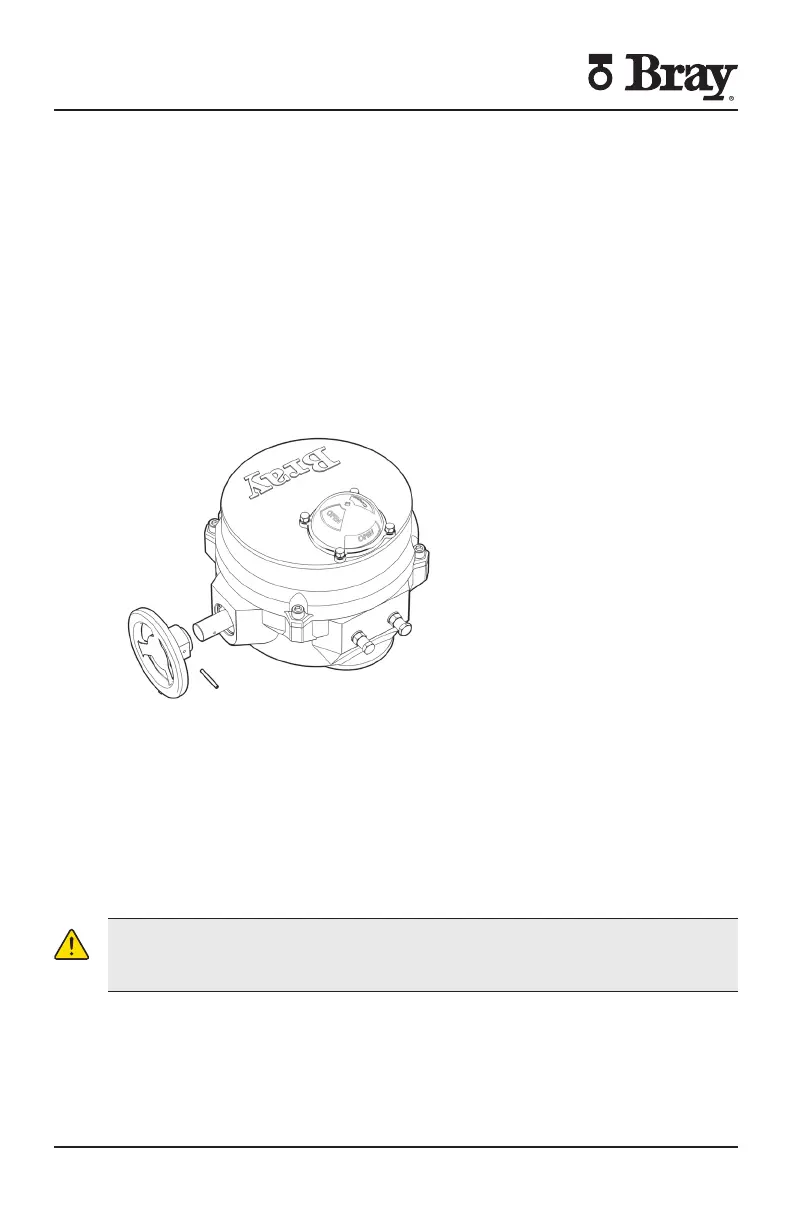
15. To remove the handwheel:
a Engage the handwheel
b Use a punch to remove the slot spring pin
i Actuator Size E E E ” [ mm]punch
c Slide the handwheel o of the override shaft
Figure S with handwheel removed
16. To replace the handwheel:
a Engage the override shaft
b Slide the handwheel onto the override shaft and align mounting holes
c Use a punch to fit a replacement slot spring pin
i Actuator Size E E E slot spring pin -
ii Actuator Size E E E slot spring pin -
iii Actuator Size - slot spring pin -
d Disengage the handwheel
CAUTION
Further disassembly of the unit requires special tools and procedures and thus will
not be covered in this manual

 Loading...


