SERIES 70 ELECTRIC ACTUATOR
Installation, Operation, and Maintenance Manual
31 of 48
© 2022 BRAY INTERNATIONAL, INC. ALL RIGHTS RESERVED. BRAY.COM
The Information contained herein shall not be copied, transferred, conveyed, or displayed in any manner
that would violate its proprietary nature without the express written permission of Bray International, Inc.
12. To replace the worm shaft spur gear:
a Slide the gear onto the end of the worm shaft
b For Actuator Size E E E
i Slide the gear (-) onto the end of the worm shaft
ii Align the mounting hole on the gear and the shaft
iii Use a [ mm] punch to replace the slot spring pin (-
)
c Actuator Size E E E
i Slide the gear (-) onto the end of the worm shaft
ii Align the mounting hole on the gear and shaft
iii Use a ” [ mm] punch to replace the dowel pin (-)
iv Replace the spiral retaining ring (-)
d Actuator Sizes -
i Rotate the handwheel so that the keyway is visible and facing upwards
ii Replace key (E-)
iii Slide the gear (E-) onto the worm shaft
iv Replace bowed E-clip retaining ring (-)
13. To remove the output drive worm wheel:
a Follow after removing the switch plate
b Back o both mechanical travel stops
c Remove the retaining ring and thrust washer from the bottom of the base
d Lift the output drive worm wheel out of its base
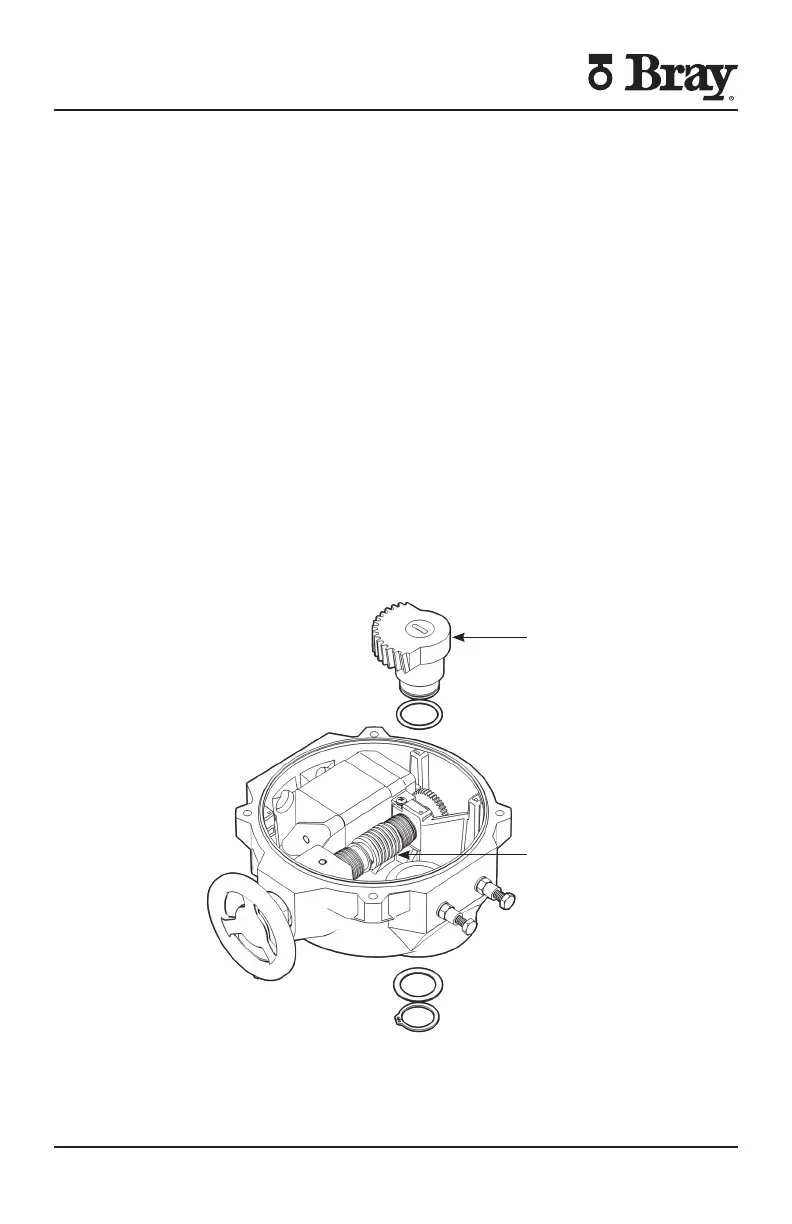
Worm Wheel
Worm
Figure S Actuator Size E E E – output drive worm wheel and spur
gear removed

 Loading...


