Do you have a question about the BRINKS BHS 2000A and is the answer not in the manual?
Description of the BHS-2000A alarm system and its components.
Details the ACP's capabilities, including zones and communication.
Guidance on physically mounting the control panel and remote units.
Specific advice for locating and securing the ACP.
Explains zone programming and alert mode functionality.
Covers master codes, entry/exit times, and other system settings.
Describes the automatic reset function for fire alarms.
Explains disabling and remotely restoring panel functions.
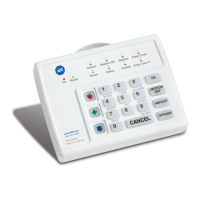
Details the SCS unit, its aesthetic placement, and installation.
Explains the 4-wire connection and cable length limitations.
Covers the 32-channel communicator, phone numbers, and programming.
Provides terminal color-to-function mapping for line connection.
Lists physical dimensions, power requirements, and zone count.
Important considerations for using the zone expander, like fire zones.
Explains AC input, bell/siren outputs, and common terminals.
Details connections for zones 1-4 and SCS keyboard.
Continues the description of zone connections from 5 to 8.
Specifies battery type, charge current, and life expectancy.
Visual representation of all electrical connections and components.
Discusses preprogramming and direct connection to PC.
Explains how to perform remote downloading via phone.
Introduces the optional programmer and its connection.
Explains using the keypad for data entry and location display.
Describes alternating between location and data views.
Explains how to move through locations and enter data.
Provides a reference for quick programming addresses and values.
Lists settings for zone types and options.
Details reporting options and special system features.
Covers phone numbers, account codes, and access codes.
Lists various timer durations and delay options.
Defines standard burglary loop behaviors like Exit/Entry and Instant.
Defines Nomad, Day/Night, and Medical loop functions.
Defines Assault, Auxiliary, Duress, Fire, and Local loops.
Explains zone types 13 and 14.
Details specific settings for zone reporting and chimes.
Covers master code reprogrammability and siren exit tone.
Details keypad options, zone expander, and panel features.
Covers false alarm prevention and force nomad features.
Explains bypass, power-up arm, and quick arm settings.
Lists phone enable settings for various event types.
Details reporting for opening, closing, and trouble events.
Explains EEPROM loading and microprocessor date information.
Explains auxiliary, installer, and master access codes.
Details standard bypass, bypass enable, and special bypass zones.
Covers programming phone numbers and dialing attempts.
Details communicator disable, DTMF, and SIA format.
Lists programmable durations for alarms and delays.
Explains the method for entering time values in hexadecimal.
Addresses problems with no indications or low/no auxiliary power.
Covers CP display, siren not working, and battery status.
Lists UL requirements for components and wiring.
Details UL-required programming settings.
Specifies California State Fire Marshal requirements.
Lists ULC requirements for components and wiring.
Details ULC-required programming settings.
Lists operating voltage, power, dimensions, and temperature.
Details physical size and operating temperature.
| operating voltage | 16.5 VAC |
|---|---|
| standby power | 12 VDC, 4 AH or 8 AH Gel Cell |
| auxiliary and fire power | 12.5 VDC at 330 mA (20VA) or 500 mA (25VA) |
| alarm output | Internal Siren Driver, 4 ohms maximum |
|---|---|
| bell output | 12 VDC, 400 mA max (20VA) or 500 mA max (25VA) |
| supervised zones | 8 |
|---|---|
| maximum zone current | 3 mA |
| RFI and transient suppression | Built in |
| operating temperature | 32-120 deg. F |
|---|---|
| enclosure material | 20 Gauge steel |
| system control station material | High impact ABS plastic |
| dimensions of BHS-2000A | 9"W x 13"L x 3"D |
|---|---|
| dimensions of DCU-602B | 6 3/8"W x 4 11/16"L x 1"D |