6-4
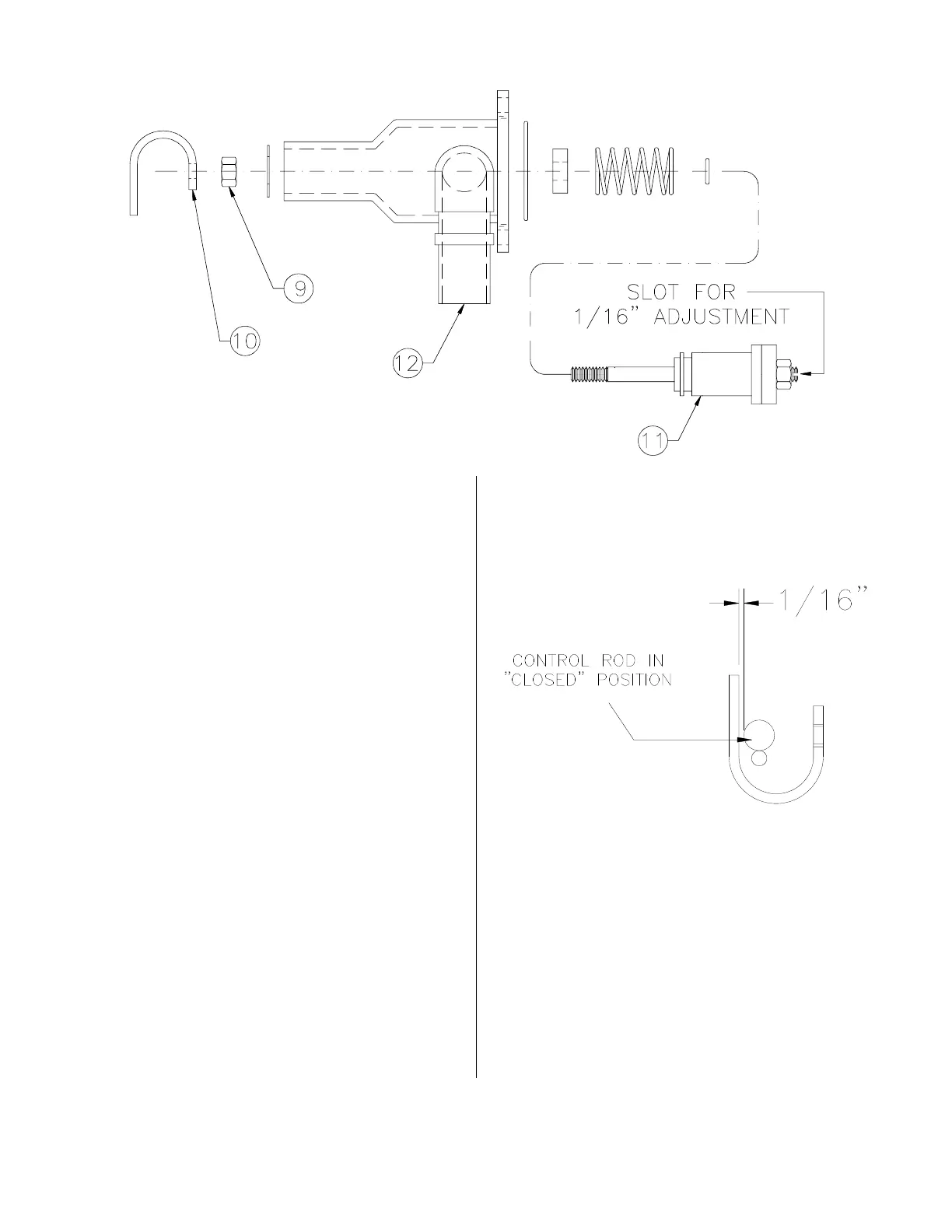
Use repair kit #15279.
1. Remove two allen screws which attach
the valve assembly to the cooking well.
2. Remove valve from the unit.
3. Loosen locking nut (9) then remove
valve control yoke (10) from the stem
assembly (11).
4. Remove entire stem assembly from the
housing (12) by pushing on threaded
end of the stem assembly.
5. Remove all components from the stem
assembly (11).
6. Clean then dry all metal components,
not replaced, with hot water and a mild
detergent.
7. Install new parts from the repair kit.
Lubricate all O-rings and contacting
surfaces with olive oil.
8. Mount valve assembly back on cooking
well with the allen screws. With the
open end of the yoke pointing to the
left.
9. With control arm in the “CLOSED”
position, a distance of 1/16” should be
maintained between the control yoke
(10) and control rod. While locking nut
(9) is loose, adjust distance in the pres-
sure port located on inside top of the
cooking well. Using a screwdriver, turn
stem assembly (11) either clockwise or
counterclockwise to obtain this dis-
tance.
10. Tighten locking nut.
Repair:
broaster.com Manual #17270 10/13 Rev 12/14