Backup power only N/A 10 years
DATA LOGGING Up to 1024 records, recorded 4/day at specific times or at defined time intervals. Record contains
date, time, rate, total, grand total, and log number.
ISOLATION All Models: 500 V opto-isolated input-to-power/OC output with
isolated input enabled
BPD6830AB2B1: 500 V input/power-to-transmitter output
ENVIRONMENTAL Operating temperature range: -40 to 75°C
Storage temperature range: -40 to 75°C
Backlight deactivated below temperatures ≈ -20°C
Relative humidity: 0 to 90% non-condensing
NON-VOLATILE MEMORY All programmed settings and total reading are stored in non-volatile memory for a minimum of ten
years if power is lost.
CONNECTIONS Screw terminals accept 12 to 22 AWG wire
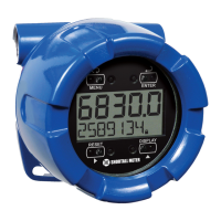
ENCLOSURE
Explosion-proof die-cast aluminum with glass window, corrosion resistant epoxy coating, color:
blue. NEMA 4X, 7, & 9, IP68. Copper-free (0.3%).
Default conduit connections: Three ¾" NPT threaded conduit openings. One ¾" NPT metal plug
with 12 mm hex key fitting installed. Additional conduit opening configurations and plugs may be
available; verify quantity and sizes on specific device labeling during installation.
MOUNTING May be mounted directly to conduit. Two slotted flanges for wall mounting or NPS 1½" to 2½" or
DN 40 to 65 mm pipe mounting. See Mounting Dimensions on page 82.
OVERALL
DIMENSIONS
5.67" x 5.24" x 4.88" (W x H x D)
(144 mm x 133 mm x 124 mm)
WEIGHT 5.00 lbs (80 oz, 2.27 kg)
WARRANTY 3 years parts and labor
Rate Input
PULSE/
TRANSISTOR/
CONTACT CLOSURE
INPUT
Field selectable; Sourcing or sinking pulse or square wave
0-5 V, 0-12 V, or 0-24 V; TTL; NPN or PNP transistor;
Open collector 100 kΩ pull-up to 3 V;
Switch contact 100 kΩ pull-up to 3 V;
PNP transistor 100 kΩ pull-down to ground (COM)
Active input 100 kΩ to battery level, 10 kΩ to power
Maximum Frequency: 64 kHz
Minimum Pulse Width: 5 µs
Threshold Setting Low (V) High (V)
Normal 1.2 2.0
Low 0.2 1.2
OPTO-ISOLATED INPUT Sourcing pulse or square wave 0-5 V, 0-12 V, or 0-24 V; Logic High: 2-24 V, Logic Low: < 1 V
Maximum Frequency: 20 kHz
Minimum Pulse Width: 20 µs
Input Current: 1 mA @ 5 V, 2.5 mA @ 12 V, 5 mA @ 24 V
LOW VOLTAGE MAG PICKUP
INPUT
Sensitivity: 20 mVp-p to 24 Vp-p
Maximum Frequency: 6 kHz
MINIMUM INPUT FREQUENCY 0.0001 Hz. Minimum frequency is dependent on high gate setting (rate display).
INPUT
IMPEDANCE
Pulse input: Greater than 75 k @ 1 kHz.
Open collector/switch input: 100 k pull-up to 3 V.
ACCURACY ±0.03% of calibrated span ±1 count
TEMPERATURE DRIFT Rate display is not affected by changes in temperature.
LOW-FLOW CUTOFF 0-99,999 (0 disables cutoff function)
DECIMAL POINT Up to four decimal places or none:
4.4444, 33.333, 222.22, 1111.1, or 00000
CALIBRATION May be calibrated using K-Factor, scale without signal source, or by applying an external
calibration signal.