2.6 Mechanical Installation
(For dimensional drawings see Appendix B: Dimensional drawings)
NOTE: When installing the Mass Flow device, care should be taken to prevent
foreign materials from entering the instrument’s inlet or outlet. Do not remove
the protective end-caps until the actual moment of installation.
When used with reactive gases (some of which may be toxic), contamination
or corrosion may occur as a result of plumbing leaks or improper purging.
Plumbing should be purged (for a signicant time) with Nitrogen before and
after use on reactive gasses.
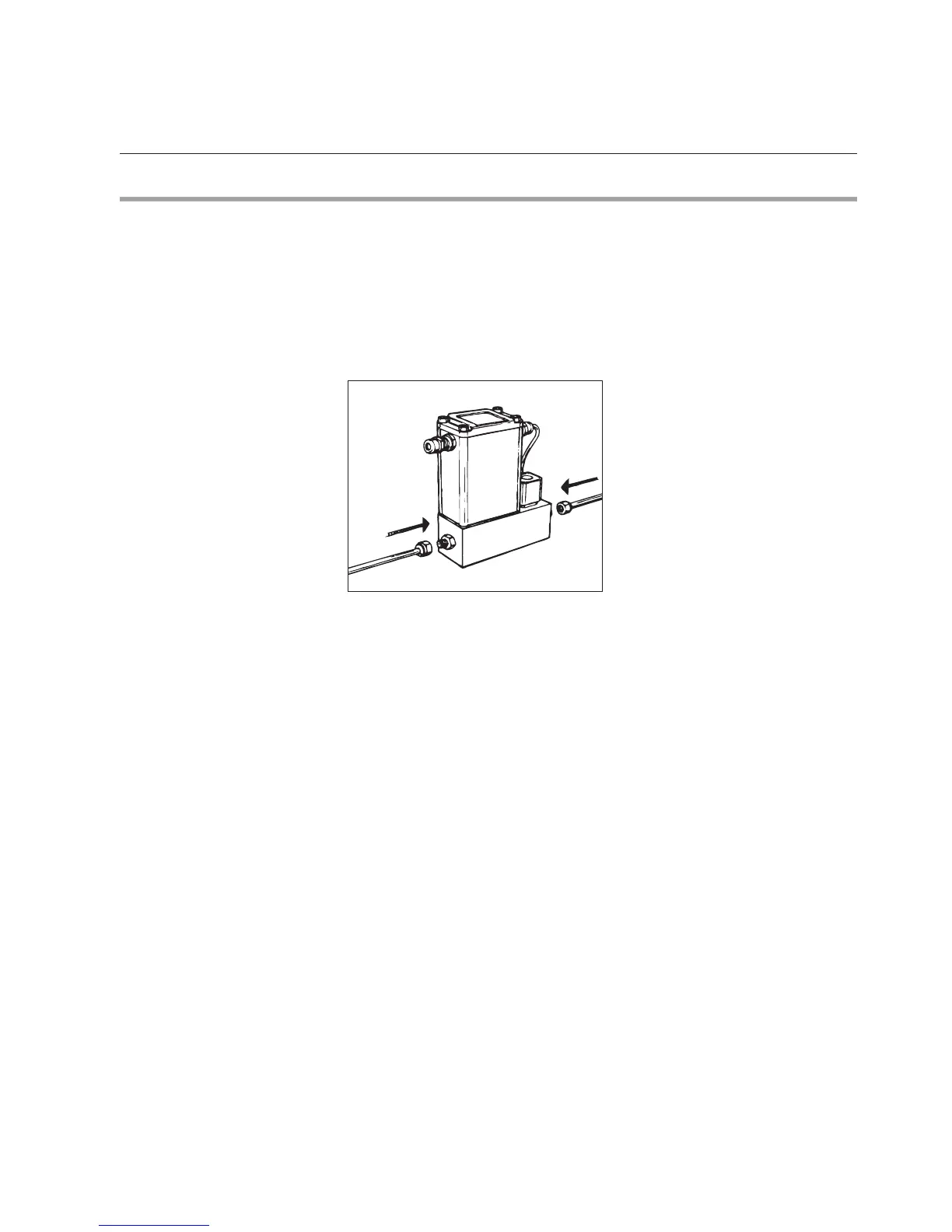
Figure 2-1: Mechanical installation
Recommended installation procedures:
a. All models should be mounted in places that are relatively free from
mechanical shocks and vibration.
b. Leave sufcient room for access to the electrical components.
c. Install in a manner that allows the instrument to be easily removed for
cleaning.
d. The mounting position of the Smart Mass Flow Meter or Controller can be
either horizontal or vertical, in case process pressures are smaller than 10 bar.
e. For higher process pressures, a horizontal installation is preferred, since
these pressures may cause a thermal siphon effect of the output signal at
zero ow conditions and degrading specications.
NOTE: The control valve of the MF-series Smart Mass Flow Controller
provides precision control and is not designed for positive shut off. If positive
shut off is required, it is recommended that a separate shut-off valve be
installed in-line, downstream from the MF-series Smart Mass Flow Controller.
NOTE: If the power supply to the MF-series Smart Mass Flow Controller
is interrupted, a NORMALLY CLOSED valve will be fully closed, while a
NORMALLY OPEN valve will be fully open. The NORMALLY OPEN control
valve meets application specic requirements, since it allows nitrogen gas
purging if the power supply is interrupted.
Section 2: Installation