2.9.2 Probus connector (MF series)
The Probus-DP electronics is hooked up via a separate M12 connector on
top of the device. This connector has IP65 protection rate and is dened in
the Probus guideline 2.142: Interconnection Technology Sepecictions.
This allows for the use of standards available, Probus approved network
connectors, enabling fast and easy connection of a Probus network Figure
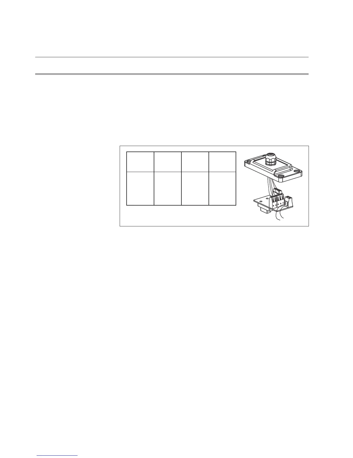
3-4 below shows the pin numbering. The connector provides the four
mandatory signals as dened in the EN 50170, i.e. RxD/TxD-P, RxD/TxD-N,
VP and DGND. The Probus signals are galvanic isolated from the main
electronics. The fth (5) connector terminal is the shieldings.
Figure 2-5: Pinnumbering