Table 2-3: Electrical connection 9-pins terminal
Signal Output (pins 4,5 and 6)
(Pin 4 and 5) indicates the ow rate, represented by a 0-5 Vdc or 1-5 Vdc
signal proportional to the mass ow. (Pin 4 and 6 ) indicates the ow rate,
represented by either a 0-20 mA or 4-20 mA signal current proportional to the
mass ow. Both the current and voltage signals are returned via (pin 4)
NOTE: I/O conguration to be dened at time of ordering. Reconguration at
customer side can be accomplished using digital communication.
NOTE: With regard to the power supply connections, the attached cable must
be as short as possible to ensure that the minimum required voltage and
current is available at the mass ow device.
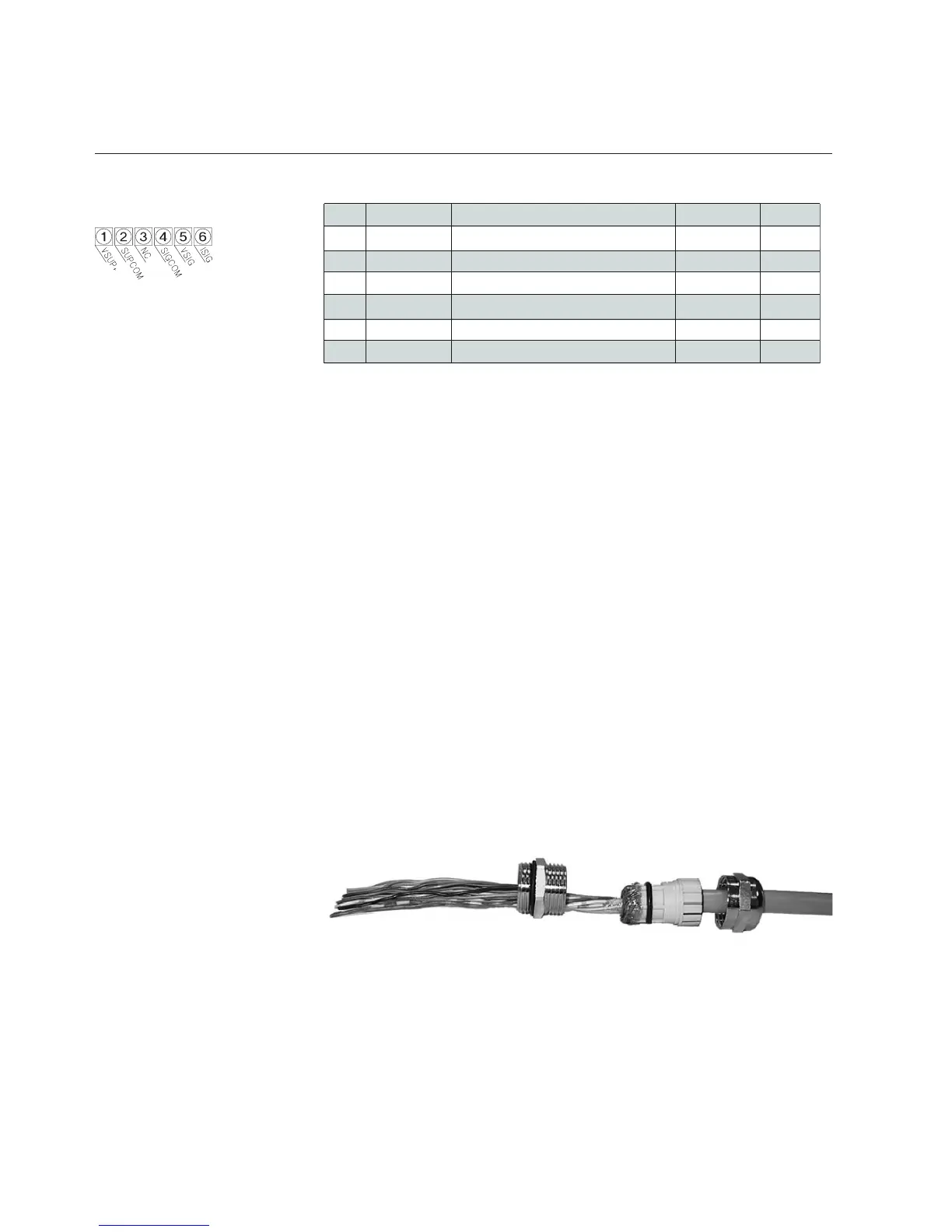
Cable Shielding Earth
Cable requirements
Compliance with EMC directive 89/336/EEC, requires that the equipment be
tted with fully screened signal cables with at least 80% shielding. The cable
shielding should be connected to the PG connector’s metal shell, and have
360° shielding at both ends. The shielding should be connected to an earth
terminal.
For translations of this instruction, see Appendix D: Translations of CE
Marking electrical installation instructions.
pin *Function Controller Meter
1 VSUP
+ 15 Vdc to +28 Vdc Power supply ••
2SUPCOMPower supply common••
a.na.ndevreseRCN3
4SIGCOM Flow signal output common ••
5 VSIG0 (1)-5 Vdc Flow signal output• •
6ISIG0 (4)-20 mA Flow signal output ••
* Abbreviation for the function description can be found under the top cover