2.7 In-Line Filter
An in-line lter is installed, as standard, in the instrument’s inlet to prevent any
foreign material entering the ow sensor or control valve. The ltering element
should be periodically replaced or ultrasonically cleaned. Apply only clean
gasses on Mass Flow Meter / Controllers.
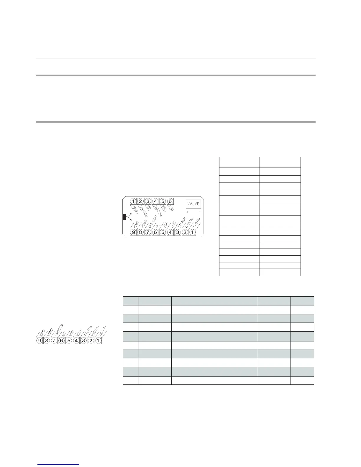
2.8 Electrical Interfacing (not for Probus)
The installation of Smart TMF involves connecting to terminal strips. For
details of correct installation, see gure 2-2 and Table 2-2, 2-3 and 2-4.
Table 2-1: Pin conguration
Figure 2-2: Electrical compartment
Table 2-2: Electrical connection 9-pins terminal
PIN NO: FUNCTION
1 VSUP +
2 SUPCOM
3 NC
4 SIGCOM
5 VSIG
6 ISIG
1 TxD / A+
2 RxD / A-
3 TTLALM
4 VREF
5 VOR
6 NC
7 CMDCOM
8 VCMD
9 ICMD
pin *Function Controller Meter
1TxD/A+RS-232/RS-485 TxD/A+ ••
2RxD/A-RS-232/RS-485 RxD/A- ••
3 TTLALM(TTL) Open collector alarm output ••
4VREF+5 Vdc ref. output••
5VOR Valve override input•n.a.
••detcennoc toNCN6
7CMDCOMSetpoint return (-)•n.a.
8VCMD0 (1)-5 Vdc Setpoint input (+)• n.a.
9ICMD0 (4)-20 mA Setpoint input (+) •n.a.
* Abbreviation for the function description can be found under the top cover