2.10 Digital Communication
NOTE: The printed circuit boards only need to be recongured if the hardware
settings differ from those specied at the time of ordering.
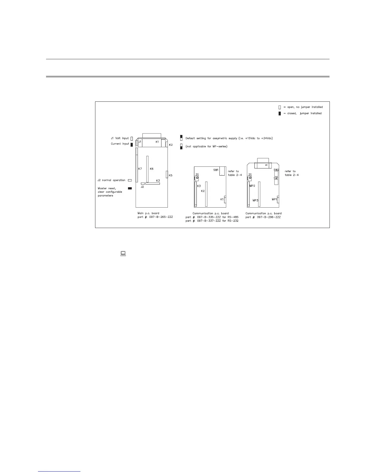
Figure 2-6: p.c. boards with the locations of jumper switches. note: Switch number 1 is the lowest switch
of four (4)
Brooks MF-series Smart Mass Flow Meters and Controllers incorporate two
printed circuit boards: one main board containing the processor and a piggyback
board. The piggyback board enables the device to communicate with a PC via
an RS-232 or RS-485 connection. The piggyback board is installed via the K5,
K6 and K7 connectors on the main board (see Figure 2-6).
The digital communication piggyback board is used for all communication-
related hardware settings. For this purpose, the board is equipped with a
dipswitch block (SW1) holding 4 switches. RS-232 Board (097-B-364-ZZZ)
or RS-485 Board (097-B-363-ZZZ), and to select the baud rate. Table 2-4
summarizes the possible settings.
Section 2: Installation