Section 2: Installation
Digital communication (pins 1 and 2)
(pins 1 and 2) are available for connecting the device to the TxD/A+ or
RxD/A-lines for RS-232/RS-485 communications.
NOTE: Either RS-232 or RS-485 should be specied at the time of ordering.
See section 2.7 for details of how to congure the p.c. board.
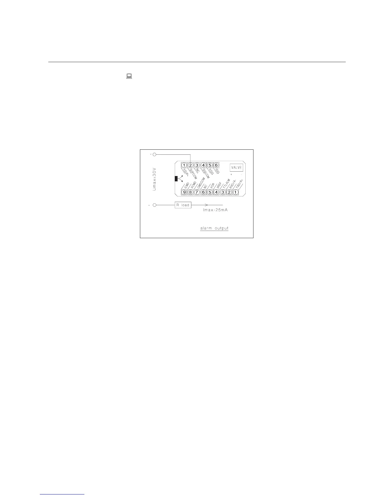
Alarm (pin 3)
A (TTL) Open Collector alarm output is available.
Type of used transistor is NPN.
Figure 2-3: Open Collector
5 Vdc reference (pin 4)
A +5 Vdc ref. voltage is available on (pin 4). This can be used to set the Set point
with the aid of an externally locate potentiometer (10 turn 2 KOhm suggested).
Valve override (pin 5 Controller models only)
To open or close the control valve independently of the Set point signal
(e.g. for safety reasons), (pin 5) is available to carry a valve override signal.
Leave oating (i.e. not connected) to allow for normal control operation.
≥ 5 Vdc ➡ Valve Open
≤ 0 Vdc ➡ Valve losed
NOTE: The valve override command on pin 5 takes precedence over the
communication-mediated valve override command.
Analogue Setpoint Input (pins 7, 8 or 9; Controller models only)
The MF-series Smart Mass Flow Controller can be used either with a current
or voltage Set point. To use the current Set point, connect the Set point signal
to (pin 9) and the Set point return signal to (pin 7) on the terminal (jumper J1
must be in place refer to Figure 2-6). To use the voltage Set point, connect the
Set point signal to (pin 8) and the Set point return to (pin 7).
Power Supply (pins 1 and 2)
The power supply is connected via (pin 1) (+15 to +28 Vdc) and (pin 2)
(power supply common).