Section 2: Installation
2.9 Electrical interfacing Probus MF
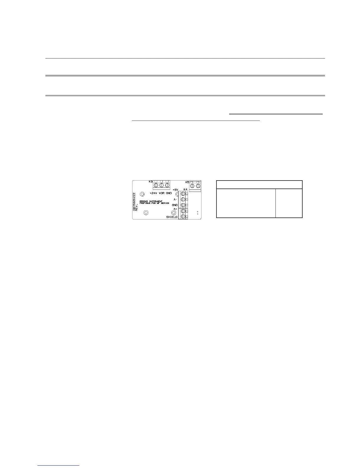
2.9.1 Main connector (MF series)
The MF series have a PG11 connector at the inlet side of the mass ow device
for the power supply and analogue I/O. In case of probus no analogue I/O is
possible, except for the Valve OverRide (VOR) input. In these cases this PG11
connector is solely used for the power supply connection and the VOR input
signal. Figure 2-4 shows the terminal connection location for power supply and
V.O.R. the power connection (as well as the probus connection terminals)
can be acces-seal by opening the top cover plate by removing the four polts
on the top of the cover plate.
The minimum requirement to operate the device on a Probus network is the
connection of the power supply lines, labeled +24V and GND.
Figure 2-4: MF Probus Main Power Connection
The valve override signal, middle screw terminal labeled VOR, can always be
used in parallel to the network. The command (OPEN,or CLOSE) issued
through this VOR terminal always takes precedence over the network valve
override command. If the level on this terminal is left oating (not connected) a
valve override command issued through the network will be carried out.
NOTE: With regard to the power supply connections, the attached cable must
be as short as possible to ensure that the minimum required voltage and
current is available at the mass ow device.
Cable Shielding Earth
Cable requirements
Complaince with EMC directive 89/336/EEC, requires that the equipment be
tted with fully screened cables with at least 80% shielding. The cables with
at least 80% shielding. The cable shielding should be connected to the PG
connector’s metal shell, and have 360 shielding at both ends. The shielding
should be connected to an earth terminal.
For translations of this instruction, see Appendix D of the MF series Instruction
and Operation manual p.n. #541-C-061-AAG: Translations of installation
instructions.