6. Replacing Parts
Disassembling and assembling the Ink Cartridge Base Unit
216
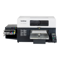
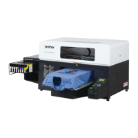
GT-3 Series
Procedur
e
1.
Remove the eight Connectors of the Harness: Ink Sensor (1) form the Ink Sensor PCB Assy (2).
2. Remove the four screws (3) and remove the Ink Switch Dog.
<Note>
There are three types for mounting the Ink Switch Dog: Pattern 1, 2 and 3. (Refer to “6-1-34. Ink Switch
Dog”.)
3. Remove the eight Screws (4) and dismount the eight Ink Sensor PCB Assys (2).
4. Remove the eight Screws (7) and dismount the Connecting Plate (8).
5. Remove the eight Screws (9) and dismount the Back Connecting Plate (10).
6. Remove the three Screws (5) and dismount the Needle Bracket (6).
<Note>
Pay attention not to put dust or dirt into the Needles. Cover the edge of the Tubes with the Caps listed
below.
Disassemble the Needle Bracket (6) here if necessary. (Refer to “6-1-36. Needles”.)
Boss section
Ink Switch Dog section
Boss section
12 Mountin
18 Mounting position
Boss section
7
5
5
5
7
Ink Cartridge Base
 Loading...