98
ELECTRICAL AND IGNITION
CHARGING SYSTEM TESTS
Auxiliary Battery Charge Wire
The auxiliary battery charge feature requires aux-
iliary battery charg e kit, P/N 500625 3 (or equiva-
lent).
IMPORTANT: Disconnect all accessories fro m
the auxiliary battery. Auxiliary battery must read a
minimum of 8.5 V at the beginning of these tests
and remain connected to th e outboard during the
tests.
Check battery ground cable for continuity.
With the key switch OFF, check battery voltage at
auxiliary battery , th en che ck voltage at auxilia ry
battery conne ction. If the rea dings are no t the
same, replace wire t o auxiliary ba ttery. The auxil-
iary battery wire must be at least 10-gauge and it
must be prote cted by a 50 A fuse or circuit
breaker at the battery.
With outboard running at 1000 RPM, voltage must
read higher than with key OFF and increase
steadily t o appr oximately 1 4.5 V as the outboard
RPM increases.
If there is no increase, turn the key switch to OFF
and test red/black wire between the EMM an d
auxiliary battery connection.
• Continuity indicates fa ulty ou tput from EMM.
Check 12 V altern ator ou tput before replacin g
EMM for faulty auxiliary b attery, charge isolator
circuit.
• No continuity indicates faulty wiring.
55 V Alternator Circuit
Check battery ground cable for continuity.
With the key switch ON, che ck battery voltage at
battery (12 V).
Then, use Ele ctrical Test Probe Kit, P/N 342677,
and a dig ital multimeter set to read 55 VDC to
check voltage on white/red wires at J2 connector
of EMM. V oltage at EMM conne ctor should b e
approximately 30 V.
With o utboard ru nning a t 1 000 RPM, voltage on
white/red wires should increase to 55 V . Voltage
readings at a sp ecific spe ed (RPM) should be
steady.
If there is any other reading, refer to STATOR
TESTS on p. 96. Inspect the st ator wiring a nd
connections. Inspect the capacitor wiring, connec-
tions, and capacitor. Repair the wiring or replace a
faulty capacitor, stator, or EMM.
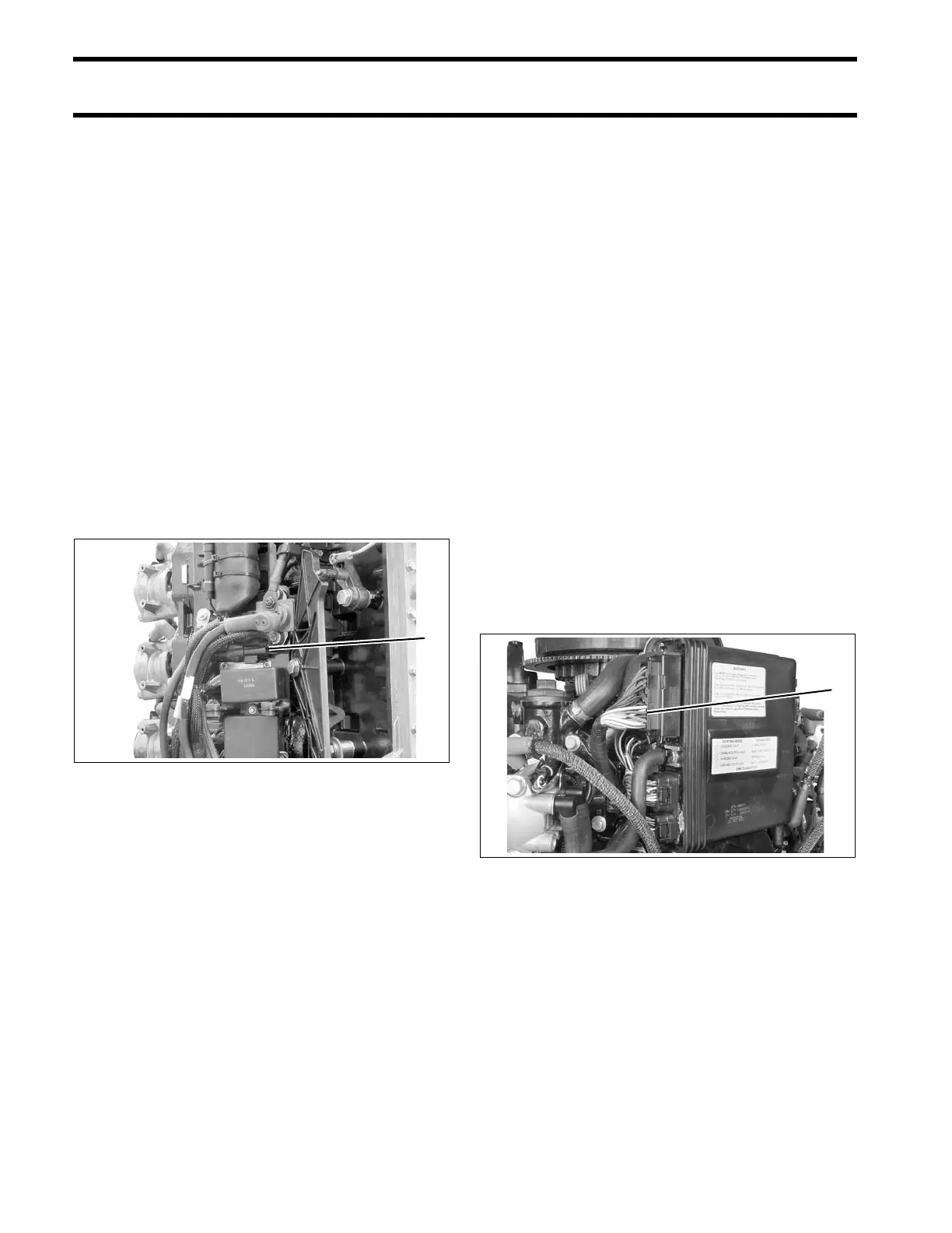
1. Auxiliary battery charge wire connection 004329
1. J2 connector of EMM 004197