106
ELECTRICAL AND IGNITION
SystemCheck CIRCUIT TESTS
SystemCheck CIRCUIT
TESTS
Make sure the SystemCheck engine monitor can
alert the opera tor durin g a “NO OIL,” “W ATER
TEMP” or “HOT ,” “CHECK ENGINE,” or “LOW
OIL” condition. Check the condition of the warning
system and associated wiring and connections.
Test the engine monitor regularly and anytime you
suspect an alert situation has been missed.
The instrument harness must be connected to the
outboard be fore perfo rming the following test s.
Refer to the Engine W iring diag ram and the
MWS Instrument W iring diagram in th e back of
this manual.
IMPORTANT: Use jumper wires ma de with the
appropriate terminals to test the warning circuits.
Gauge Self-Test Check
Turn the key switch to ON with the outboard NOT
running. The gauge warning lig hts for NO OIL,
WATER TEMP, CHECK ENGINE, and L OW OIL
must a ll ligh t at once, th en turn off in se quence,
and the warnin g hor n mu st sound for one-half
second.
If the gauge lig hts do not turn on, turn the key
switch OFF. Disconnect the gauge 8-pin connec-
tor from the back of the gauge an d turn the ke y
switch ON. T est for b attery volt age be tween
instrument harne ss terminal 1 (purple wire) and
terminal 2 (black wire).
• If battery voltage is present, replace the gauge.
• If there is no battery voltage, check that 12 V is
present at terminal “B” of the key switch. Check
condition of the instrument harness, key switch,
and connections.
If the lights worked, but the warn ing horn did n ot
sound fo r one-h alf seco nd, turn the key switch
OFF. Disconnect the warning horn 2-pin connec-
tor. Substitute a known good warning h orn. Turn
the key switch ON.
• If the substitute horn beeps, the original horn is
defective and must be replaced.
• If the subst itute horn does not beep, check for
battery vo ltage between instrument harness 2-
pin con nector, terminal 2 (purple wire) a nd
ground with the key switch ON. Also, check t he
tan/blue wire for continuity between pin 8 of the
8-pin connector a nd pin 1 of the 2-pin connec-
tor.
• If batt ery vo ltage is present at the purple wire
and the t an/blue wire has cont inuity bet ween
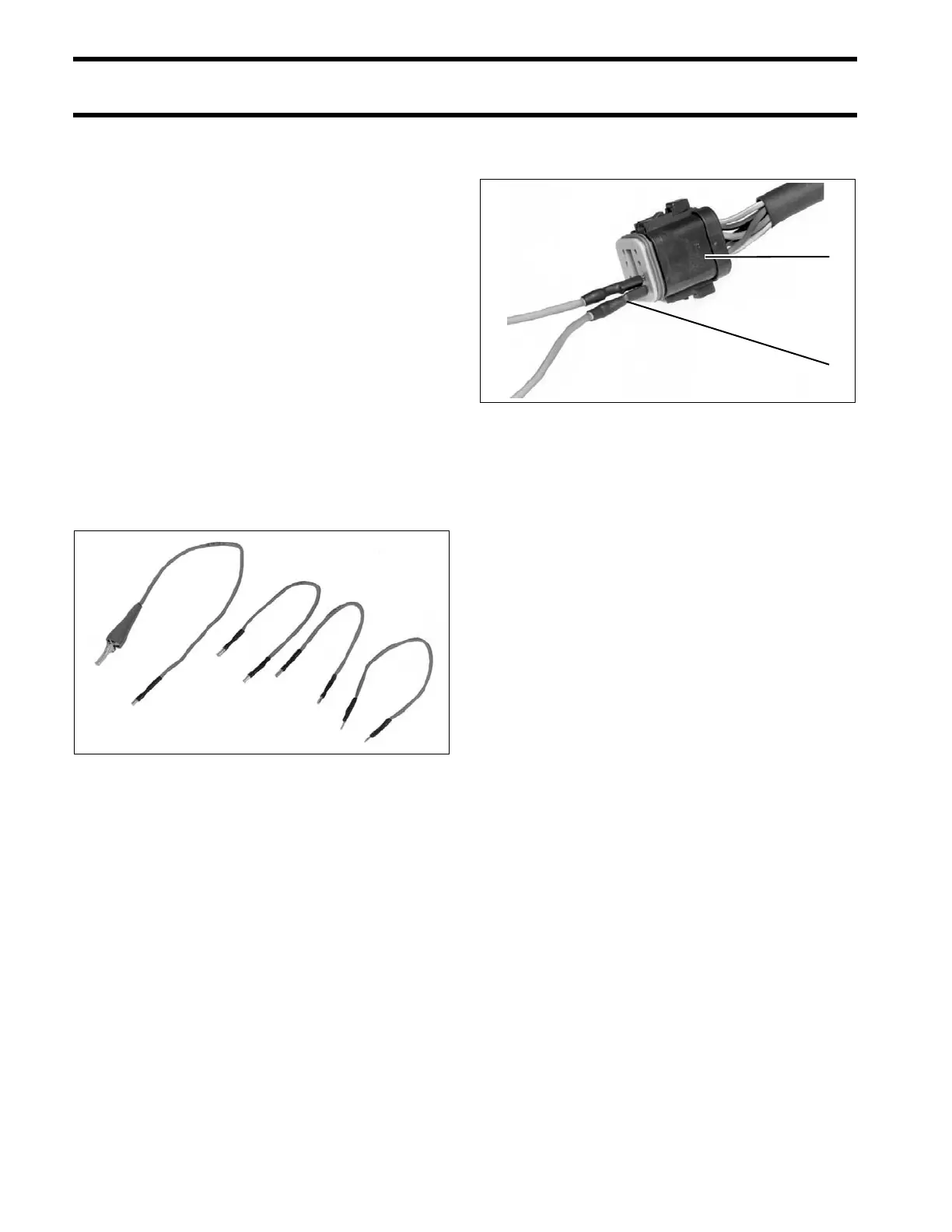
42811
1. Test adapter(s)
2. Connector, SystemCheck gauge
42761