107
ELECTRICAL AND IGNITION
SystemCheck CIRCUIT TESTS
6
the two connectors, r eplace SystemCheck
gauge.
Turn the key switch OFF and reconnect all discon-
nected circuits.
CHECK ENGINE Circuit Test
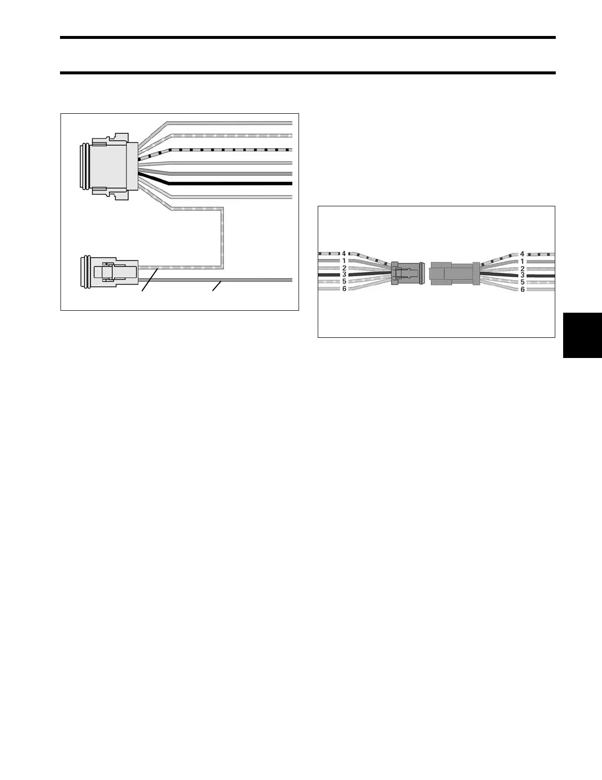
Separate th e 6 -pin SystemCheck connector of
MWS instrument harness from engine harness.
Black wire (pin 3) must be grounded.
Using a jumper wire, connect tan/orange wire (pin
2) to a clean engine ground.
Turn the key switch ON. After the normal self-test
sequence, the CHECK ENGINE light should stay
on.
• If the CHECK ENGINE light is not on, test circuit
for continuity. Check continuity of the MWS
instrument harness (tan/orange wire).
• Check cont inuity of the engine wire harness
between terminal 2 (tan/orange wire) of the Sys-
temCheck connector and pin 17 of the EMM J1-
A connector.
Turn the key switch OFF and reconnect all discon-
nected circuits.
WATER TEMP/ HOT Circuit Test
The tan wire of engine harness and the MWS har-
ness receives a signal f rom the EMM. The EMM
receives information from the temperature sensor
on the cylinder head.
Using a ju mper wire, con nect tan wire (pin 6 ) of
the engine harn ess connector to a cle an engin e
ground.
Turn the key switch ON. After the normal self-test
sequence, t he ga uge WATER TEMP / HOT indi-
cator should stay on.
• If LED is n ot on, test circuit for continuity . Test
for con tinuity of both the engine harness (t an
wire) and th e MW S instrument harn ess (t an
wire).
Turn the key switch OFF and reconnect all discon-
nected circuits.
IMPORTANT: To test the temp erature sensor
itself, refer to Engine Temperature Sensor Test
on p. 95.
1. Purple wire
2. Tan/blue wire
DRC6280
002079