236
POWERHEAD
POWERHEAD ASSEMBLY
Lubricate rod cap screw threads and under screw
head matin g su rface with a light coat of Triple-
Guard grease. App ly outboard lubricant to screw
hole threads in rod, and to screw head mating sur-
face on cap.
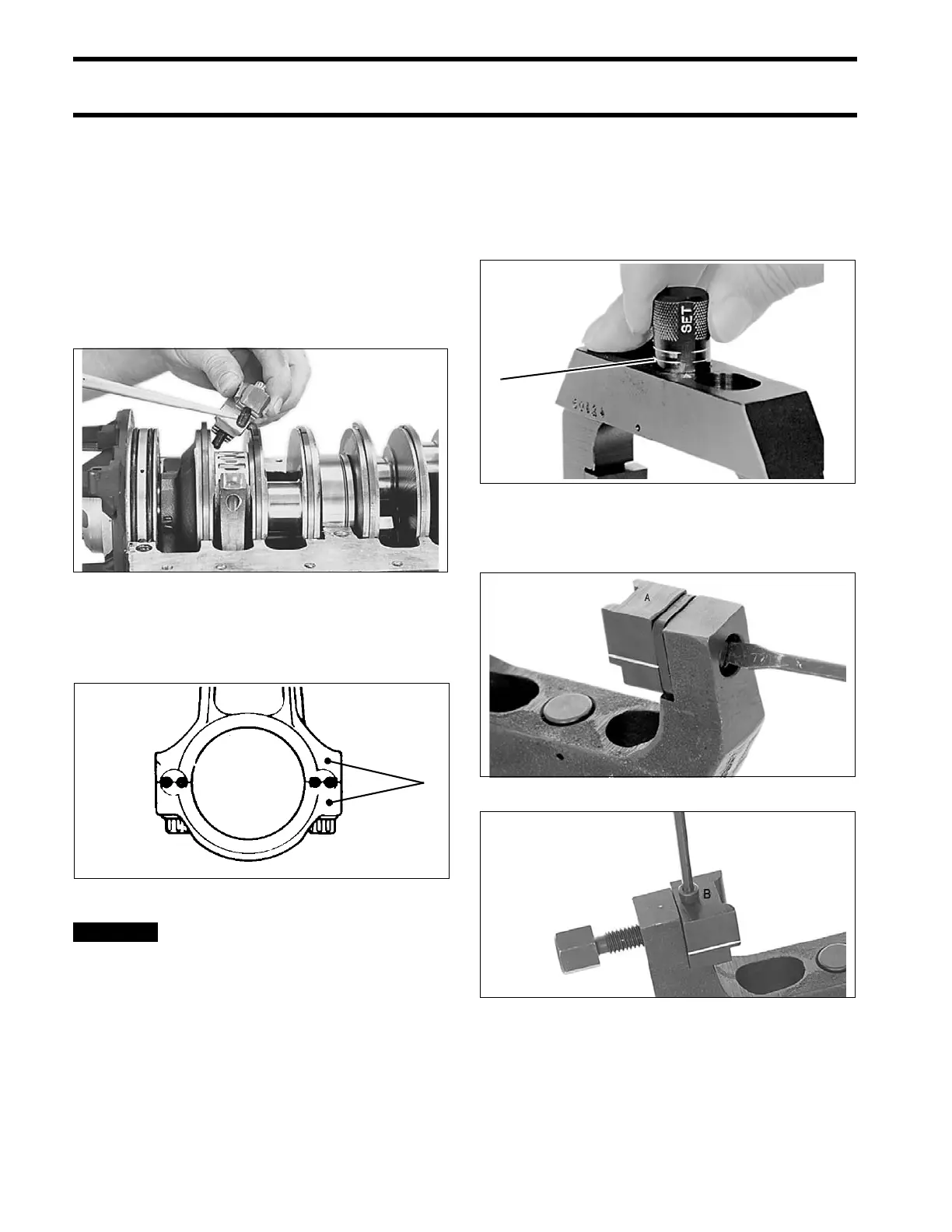
Align do t on rod cap with dot on the conn ecting
rod.
Install rod cap screws finger tight (NO MORE than
6 in. lbs. (1 N·m) maximum).
IMPORTANT: Be sure alignment dot on rod cap
matches dot o n rod and that both dot s face fly-
wheel.
Tightening rod cap sc rews without
Alignment Fixture, P/N 396749, o r us ing an
incorrect procedure c ould ca use perma nent
damage to the connecting rod and crankshaft.
To maint ain accurate torque values, keep
torque wrench extension length to a minimum.
Install Rod Cap Alignme nt Fixture, P/N 39674 9,
before tighten ing rod cap screws. Align the flat
marked “SET” on the rod adjustment stop with the
arrow on the frame. Positio n the stop at t he high-
est setting (two lines showing). Rotate adjustment
knob 180° to lock the stop in position.
Secure restraining jaw “A” and forcing jaw “B” to
frame.
31826
1. Alignment dots 53628
1. Adjustment stop, highest setting 2287
Restraining Jaw “A” 21591
Forcing Jaw “B” 21594