BÜCHI Labortechnik AG Installation | 5
Operation Manual Vacuum Pump V-600 35/65
5.13.2 Overview: setting up coolant tubing connections
The tubing connections between the various items of BUCHI laboratory equipment
form a sealed circulation system. The starting and finishing point is always the recir-
culating chiller (F-3xx).
Below is an example of the tubing connections between the laboratory apparatus.
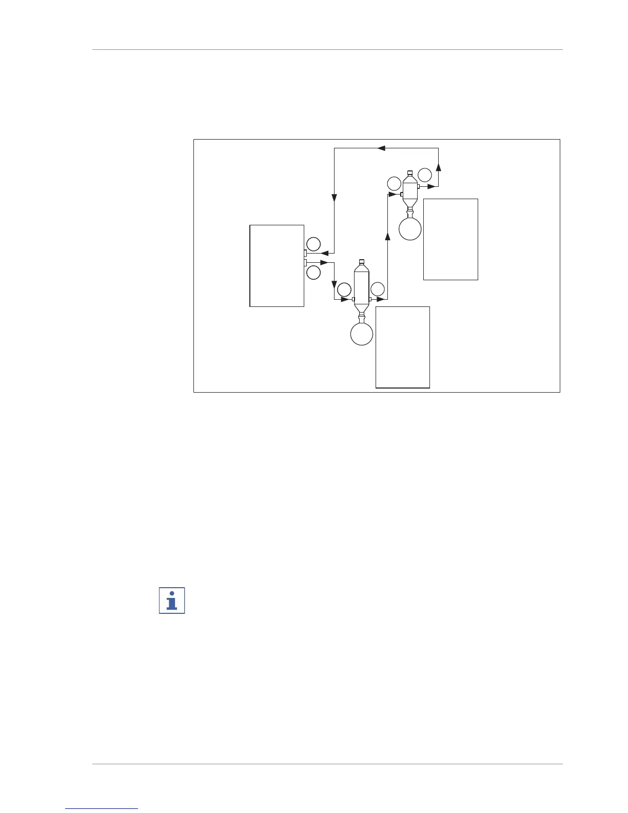
Fig.21: Coolant tubing connections in a BUCHI distillation system (example)
1 Inlet on Recirculating Chiller F-3xx 4 Condenser outlet on Rotavapor
R-300
2 Outlet on Recirculating Chiller F-3xx 5 Secondary condenser inlet on Vac-
uum Pump V-300/V-600
3 Condenser inlet on Rotavapor R-300 6 Secondary condenser outlet on Vac-
uum Pump V-300/V-600
u Connect a tube between the outlet of the recirculating chiller (2) and the inlet of
the condenser on the Rotavapor R-300 (3).
u Connect a tube between the outlet of the condenser on the Rotavapor R-300 (4)
and the inlet of the secondary condenser on the Vacuum Pump V-300/V-600 (5).
u Connect a tube between the outlet of the secondary condenser on the Vacuum
Pump V-300/V-600 (6) and the inlet of the recirculating chiller (1).
NOTE
Use GL14 hose barbs for the tubing connections.
Secure tubes with spring clips where necessary.