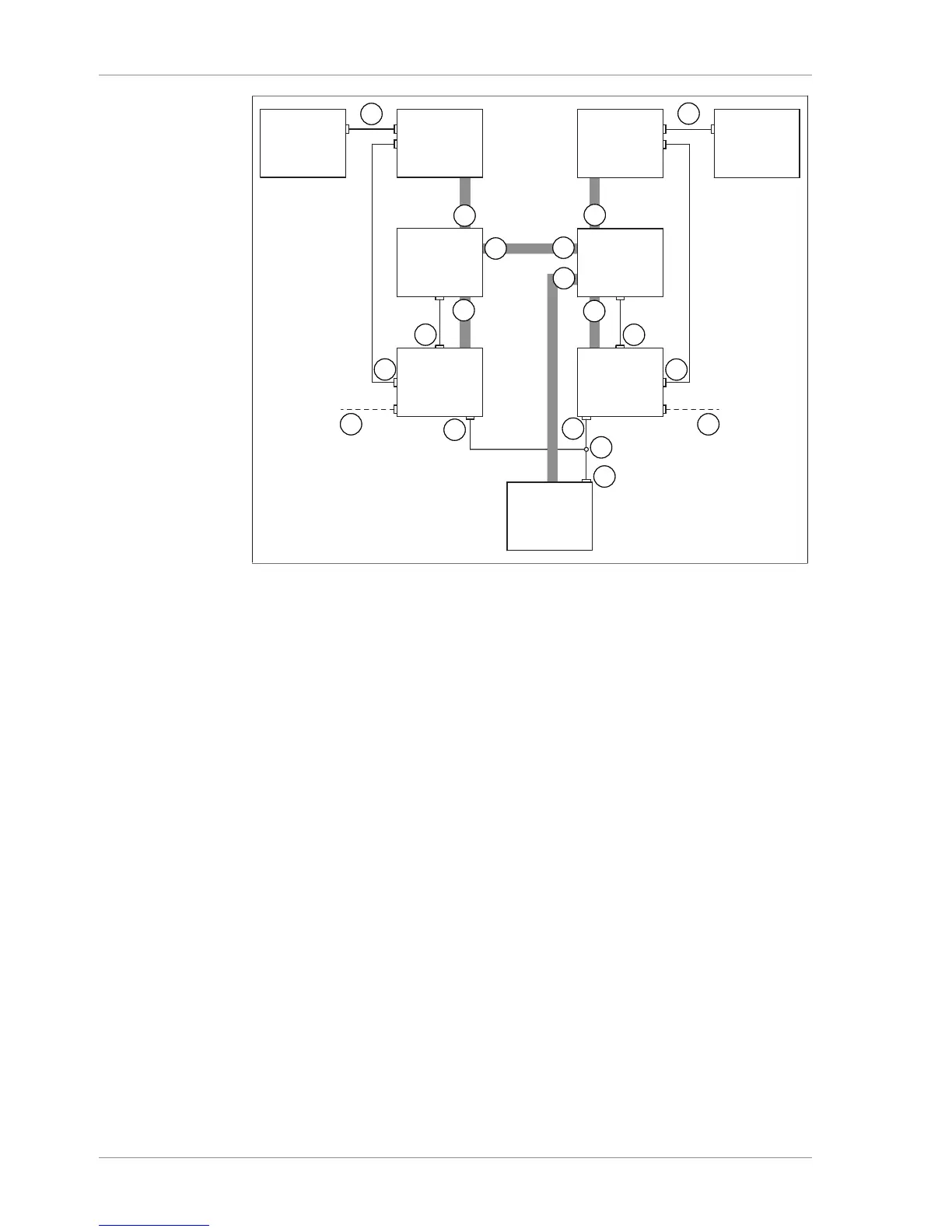
Fig.23: Schematic diagram of connections when using 2 Rotavapor systems
1 Standard BUCHI communication
ports (COM)
A Woulff bottle inlet (1)
2 Connection for valve unit (VALVE) B Woulff bottle inlet (CONTR)
3 Optional feature: Mains adaptor and
lead
C Woulff bottle inlet (2)
4 Connection for Y cable on VacuBox
(CW)
D Woulff bottle outlet (PUMP)
5 Y cable (8-pin MiniDIN CTRL)
6 Connection for alternative pump con-
troller (CTRL) on V-600
u Connect up each set of 1 Rotavapor R-300, 1 Interface I-300/I-300 Pro and 1 Vac-
uBox via the standard BUCHI communication ports (1).
u Connect vacuum tubing from each valve unit to one Rotavapor R-300 and one
VacuBox. To do so, use the CONTR inlets (B) for the Woulff bottle.
u Connect each valve unit to one VacuBox using the connection marked VALVE (2).
u Connect a tube between the two valve units. To do so, use the outlets (PUMP) for
the Woulff bottle.
u Plug a Y cable (5) into the CW connections (4) of the two VacuBoxes and connect
it to the Vacuum Pump V-600 using the CTRL connection (5).
u Connect a tube between one valve unit and the Vacuum Pump V-600. Use the
connection marked PUMP on the valve unit for this purpose.
u If a Rotavapor R-300 is not used, connect each VacuBox to the external power
supply by means of a mains adaptor (3).