Installation
Logamatic EMS RC35 programming unit - Subject to technical modifications
10
3
3 Installation
3.1 Choosing the right installation position
3.1.1 Installation in reference room
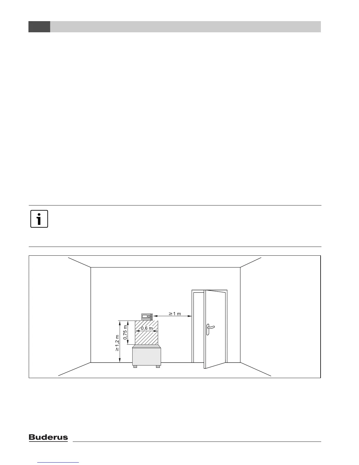
If the system is room-temperature controlled, the following requirements must be observed:
• Installation position on an internal wall (Æ Fig. 1)
• Maintain the specified distance from the door (to avoid draughts).
• Allow clearance below the programming unit (Æ Fig. 1, shaded area) (to ensure correct
temperature measurement).
• The reference room (= installation room) must be as representative as possible of the entire
home. External heat sources in the reference room (e.g. sunlight or other heat sources such as
an open fire) affect the control functions. This means it may be too cold in rooms without external
heat sources.
• Always open the thermostatic radiator valves fully in the reference room to prevent the two
temperature controllers influencing each other.
Fig. 1 Minimum clearances for installation in a reference room
If there is no suitable reference room, we recommend setting the system to weather-
compensated control instead (this requires an outside temperature sensor).
Alternatively, you could install an external room temperature sensor in the room with the
greatest heating requirements (e.g. living room).
6 720 618 477-01.1RS

 Loading...