Installation
Logamatic EMS RC35 programming unit - Subject to technical modifications
12
3
3.3 Installation and connections
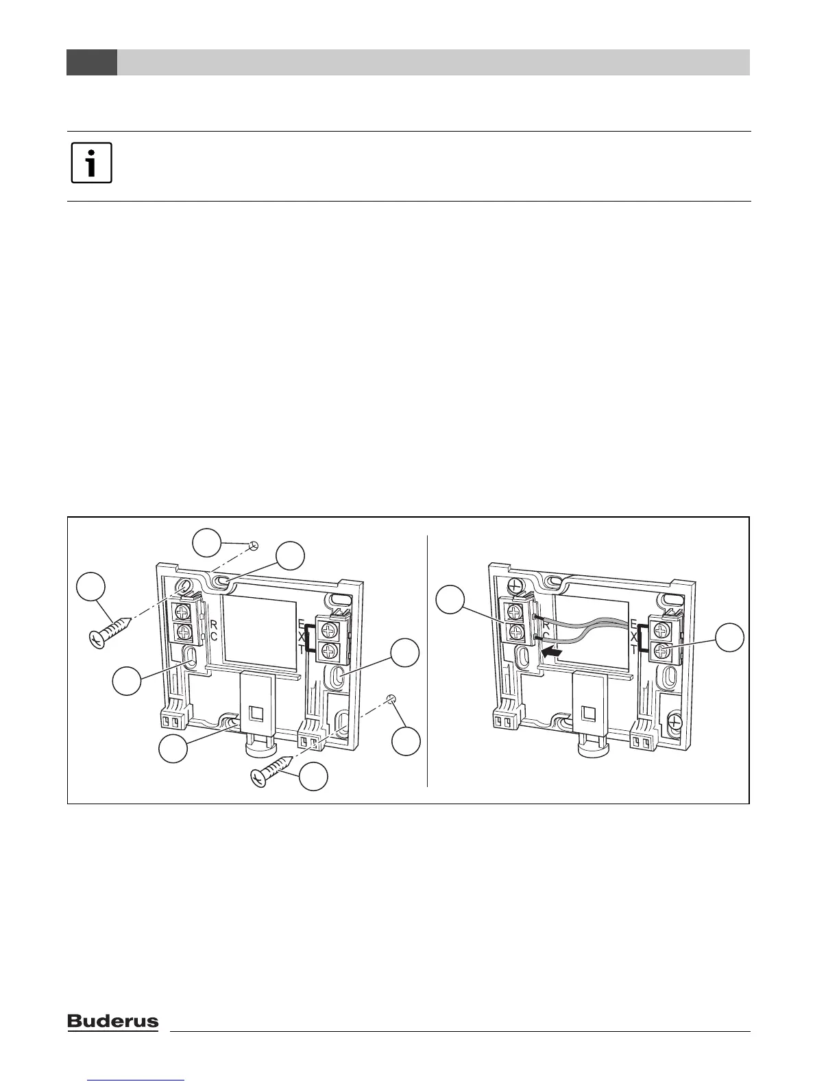
The wall mounting base can be attached directly to the wall or on a flush box.
When mounting on a flush box, note the following:
B Draught from within the flush box must not be able to falsify the capture of the room temperature
by the programming unit.
If required, stuff the flush box with insulation material.
B Use horizontal or vertical fixing holes [4].
B Fit the wall mounting base (Æ Fig. 3, left).
B Connect the two-core BUS cable from the Energy Management System (EMS) at terminals “RC”
[5].
– Cable type: 2 x 0.75 mm
2
(0.5 – 1.5 mm
2
), max. length 100 m
– Polarity is irrelevant for the two wires.
B Do not lay the cables parallel to power cables.
Fig. 3 Mounting the wall mounting base (left) and connecting the wires (right)
1 Hole drilled in the wall
2 Screws (included with the unit) for surface-mounting on the wall
3 Vertical mounting holes for mounting on a flush box
4 Horizontal mounting holes for mounting on a flush box
5 “RC” terminals for EMS (boiler)
6 “EXT” terminals for external room temperature sensor or for jumper
Only use the wall mounting base with screw terminals.
B Replace wall mounting bases without screw terminals that may already be installed.
6 720 618 477-03.1RS
2
2
3
3
4
4
5
6
1
1

 Loading...