7 Systems
6 720 646 864 (12/2010) – Technical guide Logano GE315, GE515 and GE615
44
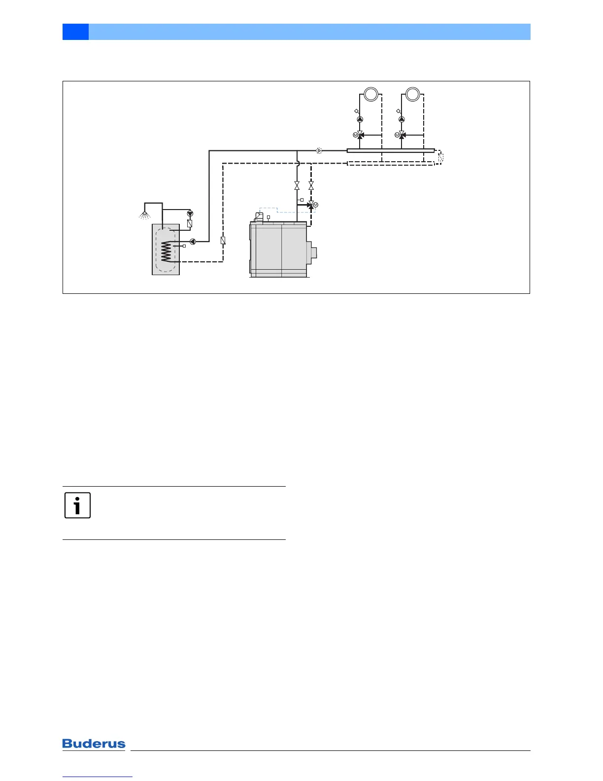
7.5 Single boiler system with boiler circuit control
Fig. 35 System example for an Ecostream cast iron boiler; DHW heating with DHW cylinder; number and version of
the heating circuits dependent on the Logamatic control unit
FK Boiler water temperature sensor
FV Flow temperature sensor
FW DHW temperature sensor
FZ Auxiliary sensor
HK Heating circuit
KR Check valve
PH Heating circuit pump
PK Boiler circuit pump
PS Cylinder primary pump
PZ DHW circulation pump
RK Return
SH Heating circuit actuator
SK Boiler circuit actuator
VK Boiler flow
1 DHW cylinder (primary store system as option)
Application area
• Ecostream cast iron boilers Logano GE315, GE515
and GE615
• Boiler circuit control with Logamatic 4311 control unit
in conjunction with third party heating circuit control or
special applications
Function description
The Logamatic control unit safeguards the operating flow
temperature of the boiler. If the operating flow
temperature at temperature sensor FK falls below the set
value when the burner is on, the control function reduces
the flow rate in the heating circuit flow with the boiler
circuit actuator SK until the operating temperature has
been reached. The burner output is regulated subject to
the temperature at the auxiliary sensor FZ and the set
value of the system.
Special design information
• This layout is ideal for modernising a system where the
operating flow temperature cannot be regulated via the
heating circuit actuators (e.g. third party control unit).
An auxiliary sensor FZ is required.
• Alternatively, the system can be designed with a
pressurised flow and return distributor. In this case, the
boiler circuit pump PK and the bypass between the
flow and return distributor are not required.
HK2HK1
KR
PS
FW
KR
PZ
SH2
PH2
SH1
PH1
KR
SK
PK
VK
RK
FV1
FV2
FK
FZ
6 720 644 097-28.1il
Logano
1
The circuit diagram is only a schematic
illustration!
For information on all system examples,
Æ page 36.
 Loading...