7 Systems
6 720 646 864 (12/2010) – Technical guide Logano GE315, GE515 and GE615
54
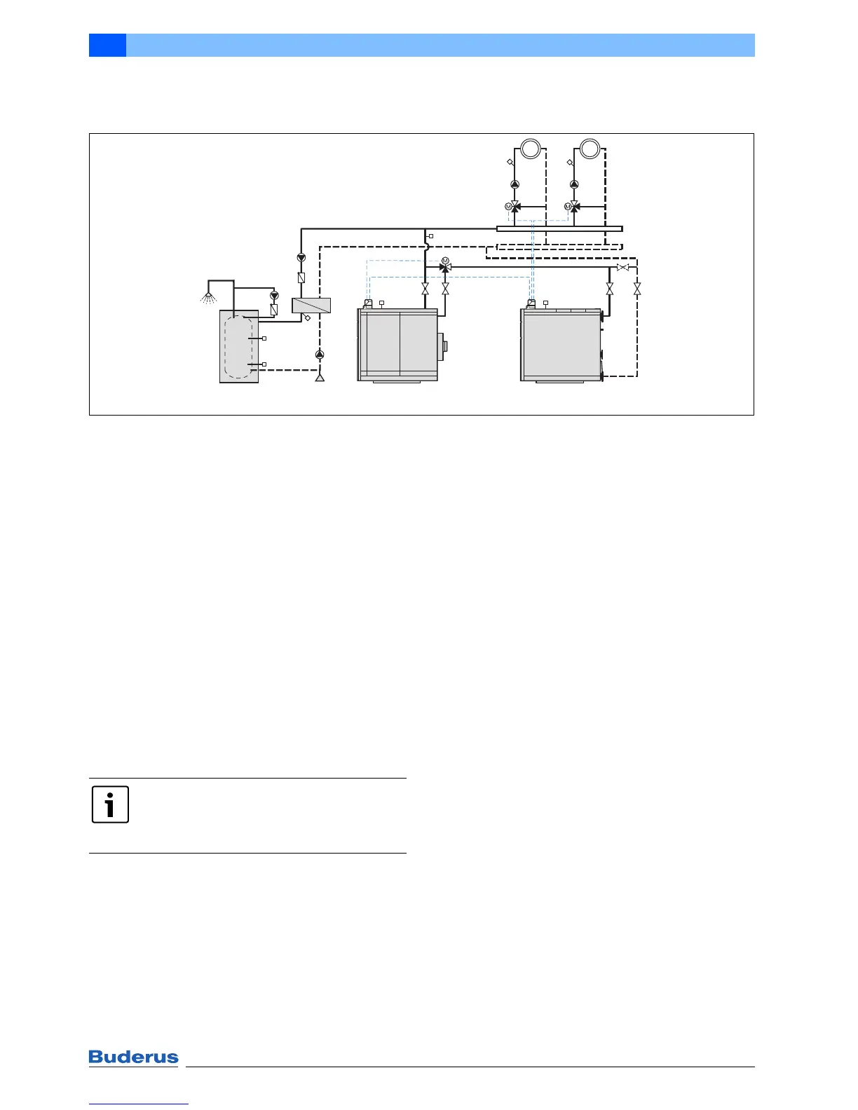
7.10 2-boiler system Ecostream cast iron boiler/gas condensing boiler with boiler
control and heating circuit control
Fig. 40 System example for an Ecostream cast iron boiler and a Logano plus SB315 or SB615 gas condensing boiler;
DHW heating with primary store system; number and version of the heating circuits dependent on the control
unit
EK Cold water inlet
FK Boiler water temperature sensor
FV Flow temperature sensor
FVS Strategy flow temperature sensor
FW DHW temperature sensor
HK Heating circuit
KR Check valve
PH Heating circuit pump
PS Cylinder primary pump
PW Stratification pump
PZ DHW circulation pump
RK Return
RK1 Low temperature return to condensing boiler
SH Heating circuit actuator
SK Boiler circuit actuator
VK Boiler flow
WT Heat exchanger
1 Gas condensing boiler
2 Primary store system (DHW cylinder as option)
1)
Inspection bypass (optional)
Application area
• Logano plus SB315 and SB615 gas condensing
boilers
• Ecostream cast iron boilers Logano GE315, GE515
and GE615
• Boiler circuit control with the Logamatic 4211 and
4312 control units, also in conjunction with third party
heating circuit control or special applications
Function description
The boiler sequence can be controlled via the multi boiler
strategy module subject to load and time. If the
temperature at the strategy sensor FVS falls below the set
flow temperature, the (1) lead boiler starts. If the heat
demand increases, the Logano (2) lag boiler is
automatically switched on.
When the operating flow temperature at temperature
sensor FK2 for the lag boiler is reached, the boiler circuit
actuator SK opens in the flow direction of the Ecostream
cast iron boiler and the entire flow rate is routed via the
Ecostream cast iron boiler. If the load falls, the switching
processes run in reverse order.
Special design information
• The boiler sequence cannot be reversed.
• Size the heating circuit pumps in accordance with the
maximum calculated pressure drop in the heating
circuit and boiler circuit (sum of the pressure drop
levels on the water side of both boilers). The pressure
drop levels of both boilers must be reliably overcome.
Alternatives for hydraulic circuits if the pressure drop
on the water side is too high are available on request.
• To keep the pressure drop on the water side low, when
sizing the heating circuits maintain a minimum spread
of 20 K.
• We recommend distributing the total output between
the boilers so each has 50 %.
• Design the connections in such a way that the boilers
can be separated, independently of each other, to
ensure an emergency supply during maintenance work.
HK2HK1
SK
1)
SH2
PH2
SH1
PH1
FK2
FK1
VK
RK1
VK RK
FVS
FV1 FV2
6 720 644 097-34.1il
Logano (2)
1 (1)
2
KR
PS
PW
FW2
KR
PZ
FW3
FW1
EK
WT
The circuit diagram is only a schematic
illustration!
For information on all system examples,
Æ page 36.
 Loading...