3-28 2005 Buell Firebolt: Engine
HOME
38. See Figure 3-31. If the crankcases are being separated it
will be necessary to remove rear isolator assembly by
removing the forward two fasteners first and then the two
rear fasteners (re-install with
new
fasteners).
39. See Figure 3-32. Place a block of wood between rear
isolator mount on main frame and swingarm/oil tank.
40. Route a ratcheting tie down through the swingarm bear-
ings, up over the main frame, through the top stabilizer
area, back down to the ratchet mechanism and secure
swingarm to main frame.
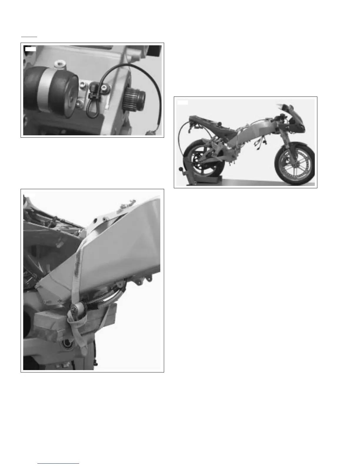
NOTE
See
Figure 3-33.
This allows the vehicle to remain together
as a rolling chassis and to be removed from the lift and stored
if necessary.
41. Remove support from under swingarm/oil tank.
42. Remove overhead support.
Figure 3-31. Rear Isolator and Mounting Hardware
Figure 3-32. Securing Vehicle for Relocation
8723a
8728
Figure 3-33. Rolling Chassis
8726