2-26 2003 Buell P3: Chassis
HOME
INSTALLATION
1. See Figure 2-27. Fasten master cylinder to handlebar by
installing clamp (2) and screws (1) (metric). Tighten to
80-120 in-lbs (9-14 Nm).
11WARNING1WARNING
● Use only new black banjo washers (See Parts Cata-
log for Part No.) with D.O.T. 4 brake fluid. Earlier sil-
ver banjo washers are not compatible with D.O.T. 4
fluid and will not seal properly over time. Failure to
comply may adversely affect braking ability and lead
to brake failure which could result in death or seri-
ous injury.
● To avoid leakage, ensure that banjo washers, banjo
bolt, hydraulic brake line and master cylinder bore
are completely clean.
2. Connect brake line (5) to master cylinder using two new
banjo washers (4) and banjo bolt (6) (metric). Tighten to
16-20 ft-lbs (22-27 Nm).
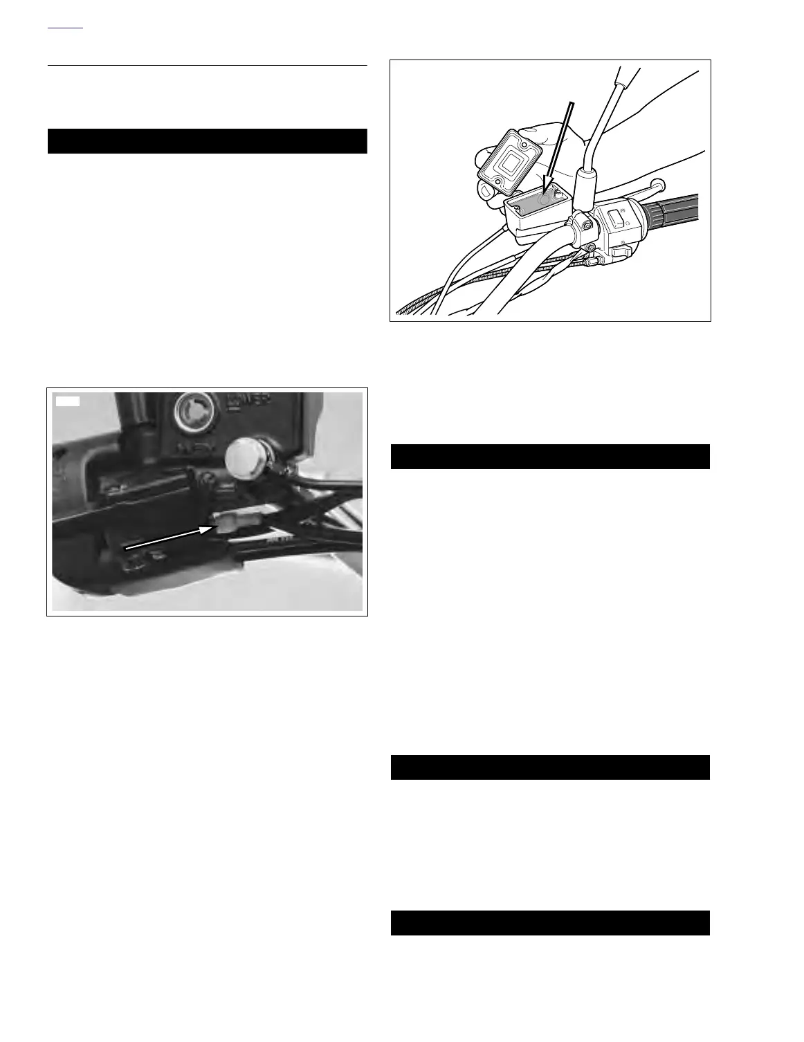
3. See Figure 2-35. Verify brake lamp switches are secure.
Attach wires to switches.
4. Install mirror parallel to handlebars.
5. See Figure 2-27. Remove the two master cylinder cover
screws (3), cover and cover gasket.
6. See Figure 2-36. With the master cylinder in a level posi-
tion, add D.O.T. 4 BRAKE FLUID. Bring fluid level to
within 0.125 in. (3.2 mm) of molded boss inside front
master cylinder reservoir.
11WARNING1WARNING
Verify proper operation of the master cylinder relief port.
A plugged or covered relief port can cause brake drag or
lockup, which could result in loss of vehicle control and
death or serious injury
7. See Figure 2-36. Verify proper operation of the master
cylinder relief port.
8. Actuate the brake lever with the reservoir cover removed.
A slight spurt of fluid will break the surface if all internal
components are working properly.
9. See Figure 2-27. Attach master cylinder cover and cover
gasket with the two cover screws (3). Tighten to 9-13 in-
lbs (1.0-1.5 Nm).
10. Bleed brake system. See 1.6 BRAKE SYSTEM MAINTE-
NANCE.
11WARNING1WARNING
Check for proper brake lamp operation before riding
motorcycle. Visibility is a major concern for motorcy-
clists. Failure to have proper brake lamp operation could
result in death or serious injury.
11. Turn ignition key switch to IGN. Apply brake hand lever to
test brake lamp operation. Turn ignition switch to LOCK.
11WARNING1WARNING
Always test motorcycle brakes at low speed after servic-
ing or bleeding system. If brakes are not operating prop-
erly, or braking efficiency is poor, testing at high speeds
could result in death or serious injury.
Figure 2-35. Brake Lamp Switch Connectors
6569
Figure 2-36. Brake Fluid Level
a0214x2x