2003 Buell P3: Electrical 7-49
HOME
HEADLAMP 7.17
REMOVAL/DISASSEMBLY
Headlamp
NOTE
The headlamp is a sealed assembly and not repairable. If
bulb fails, replace headlamp assembly.
1. Remove four screws, washers and windscreen. See 2.26
WINDSCREEN.
2. See Figure 7-63. Remove three phillips head screws and
bezel from nest.
3. Remove three screws and retaining ring.
4. Slide headlamp from headlamp housing and detach
headlamp connector from rear of headlamp.
1CAUTION
The headlamp contains Halogen gas under pressure.
Handle headlamp carefully and wear eye protection. If
the headlamp is mishandled or dropped, it could explode
which could result in mild or moderate injury.
Headlamp Housing and Brackets
1. See Figure 7-63. Remove two screws and washers and
partially remove headlamp housing from vehicle.
2. Detach connector [38] from wiring harness. Remove
headlamp housing from vehicle.
3. To remove nest, remove two adjusting screws and
detach spring from nest.
4. Remove headlamp brackets.
a. Remove front turn signals. See 7.19 TURN SIG-
NALS.
b. Remove two screws from bracket.
c. Repeat for other bracket.
d. Remove front forks and headlamp brackets. See
2.17 FRONT FORK.
e. Remove windscreen from brackets. See 2.26 WIND-
SCREEN.
ASSEMBLY/INSTALLATION
Headlamp Housing and Brackets
1. Install headlamp brackets.
a. Install front forks through triple clamps and brackets.
See 2.17 FRONT FORK.
b. See Figure 7-63. Install bracket with two allen
screws and tighten to 12-14 ft lbs (16.3-19.0).
c. Repeat for other bracket
d. Attach both front turn signals. See 7.19 TURN SIG-
NALS.
e. Install windscreen if removed with four screws and
washers. See 2.26 WINDSCREEN.
2. See Figure 7-63. Attach connector [38] to wiring har-
ness.
3. Install headlamp housing using two screws and washers.
Tighten to 12-14 ft-lbs (16.3-19 Nm).
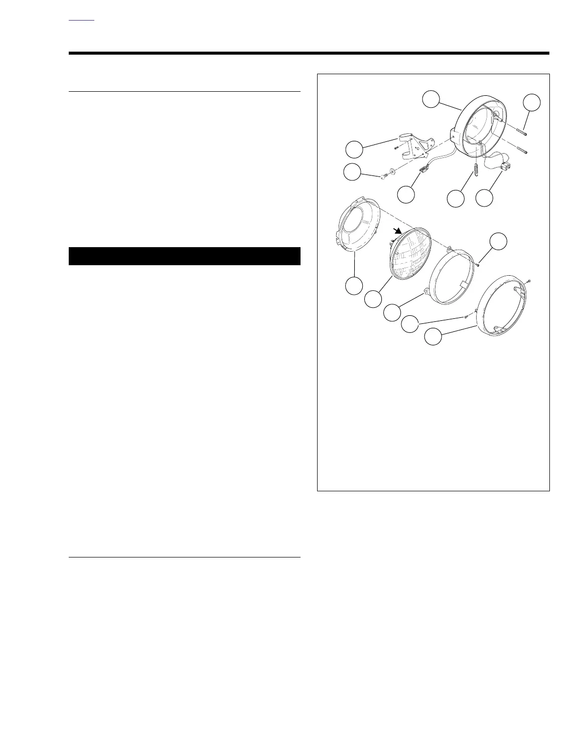
Figure 7-63. Headlamp Assembly
a0251x7x
“A”
1. Headlamp housing
2. Adjusting screws (2)
3. Headlamp connector
4. Spring
5. Connector [38]
6. Right bracket
7. Screws (2)
8. Nest
9. Headlamp
10. Retaining ring
11. Screws (3)
12. Screws (3)
13. Bezel
8
9
12
10
13
11
1
2
4
5
3
6
7