2003 Buell P3: Fuel System 4-23
HOME
THROTTLE POSITION SENSOR 4.6
REMOVAL
NOTE
For electrical diagnostics and troubleshooting, please refer to
7.4 THROTTLE POSITION SENSOR (TP Sensor).
1. Remove seat.
11WARNING1WARNING
To protect against shock and accidental start-up of vehi-
cle, disconnect the negative battery cable before pro-
ceeding. Inadequate safety precautions could result in
death or serious injury.
2. Unthread bolt and remove battery negative cable (black)
from battery negative (-) terminal.
3. Remove air cleaner assembly. See 4.3 AIR CLEANER.
4. Remove carburetor assembly. See 4.4 CARBURETOR.
5. Locate 6-place Deutsch connector in front of ignition coil
and depress external latch to separate pin and socket
halves. Remove pin terminals from chambers 3 through
5.
NOTE
For instructions on properly removing wire terminals, see
SECTION 7, ELECTRICAL, DEUTSCH ELECTRICAL CON-
NECTORS.
6. Using special TORX bit (Snap-on® TTXR20E), remove
two tamper-resistant T20 TORX screws to release throt-
tle position sensor from carburetor. Pull sensor from car-
buretor bore.
INSTALLATION
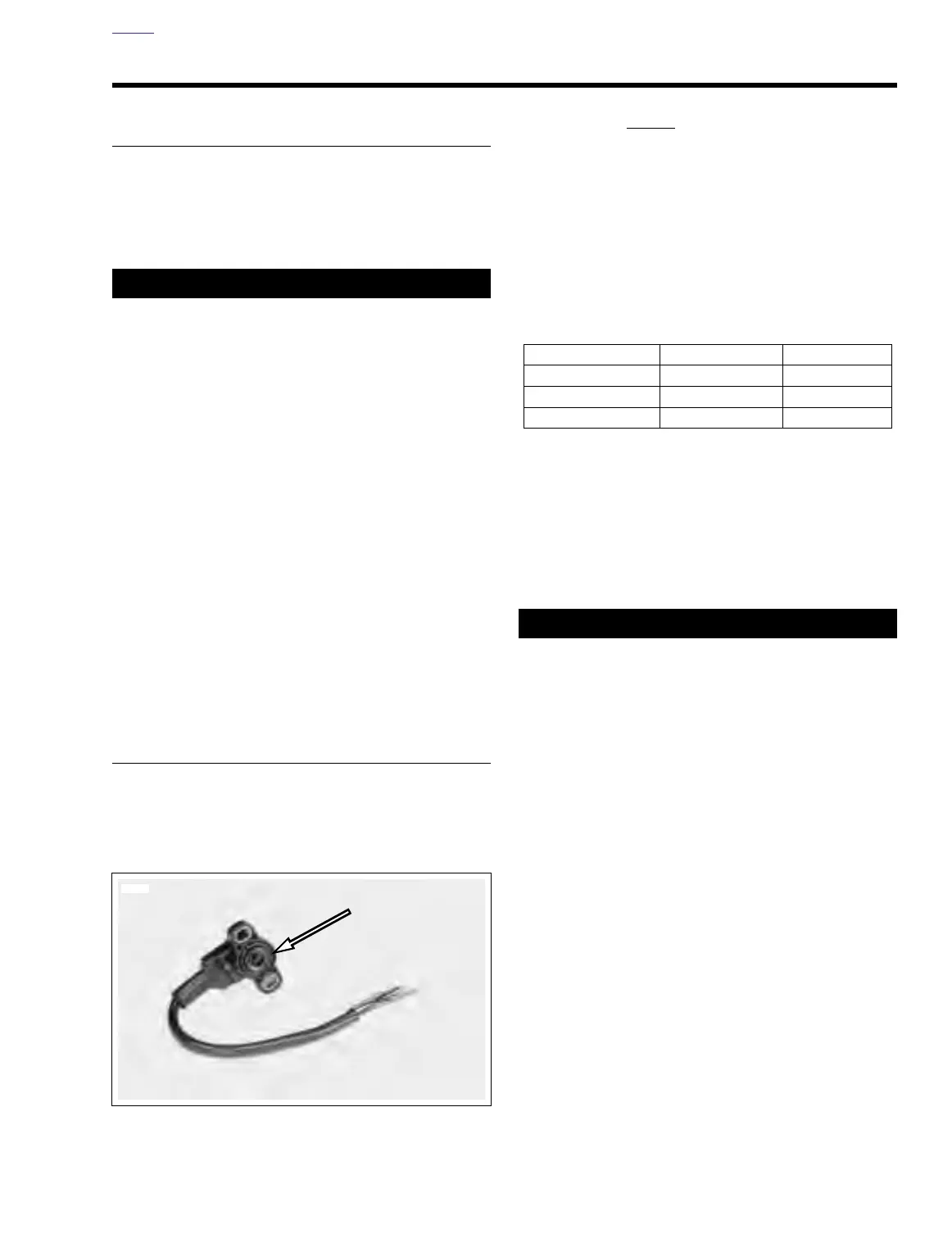
1. See Figure 4-21. Obtain new throttle position sensor. If
old sensor is used, inspect o-ring for cuts, tears or signs
of deterioration. Replace o-ring if necessary.
2. Align holes in throttle position sensor with those in carbu-
retor housing. Using special TORX bit (Snap-on®
TTXR20E), loosel
y install two tamper-resistant T20
TORX screws.
NOTE
The tamper-resistant screws are not to be tightened until the
throttle position sensor has been properly adjusted. See the
instructions under step 6 for details.
3. Locate 6-place Deutsch connector and install pin termi-
nals in chambers 3 through 5. Mate pin and socket
halves of connector.
4. Insert bolt through battery negative cable (black) into
threaded hole of battery negative (-) terminal. Tighten
bolt to 60-96 in-lbs (7-11 Nm).
5. Install carburetor assembly. See 4.4 CARBURETOR.
6. Adjust throttle position sensor. See 7.4 THROTTLE
POSITION SENSOR (TP Sensor).
7. Install air cleaner assembly. See 4.3 AIR CLEANER.
Pull up on seat to verify that it is properly secured, front
and rear. A loose seat may shift during vehicle operation
and startle the rider, possibly causing loss of vehicle
control that could result in death or serious injury.
8. Install seat.
NOTE
Be sure the engine is warmed up to normal operating temper-
ature BEFORE adjusting engine idle speed.
9. Adjust engine idle speed, as follows: With the engine at
normal operating temperature (auto-enrichener valve
closed), adjust the throttle stop screw so the engine idles
at 1200 RPM.
NOTE
To measure engine RPM, use a hand held inductive tachom-
eter to pick up the signal off the spark plug cable.
Figure 4-21. Throttle Position Sensor with O-ring
7753
Table 4-7. TP Sensor Connector
Chamber Number Wire Color Function
3 Light Blue Output
4Yellow Input
5BlackGround