Operating Instructions | 1473-1-8164
Pos: 21 / #Ne ustr ukt ur# /Onl in e-Dokumentation (+KNX)/Überschrift en ( --> Für all e D ok ument e <--) /2. E bene/ G - L/H elli gkeitss ensor @ 28\mod_1347004848616_15.docx @ 232236 @ 222222 @ 1
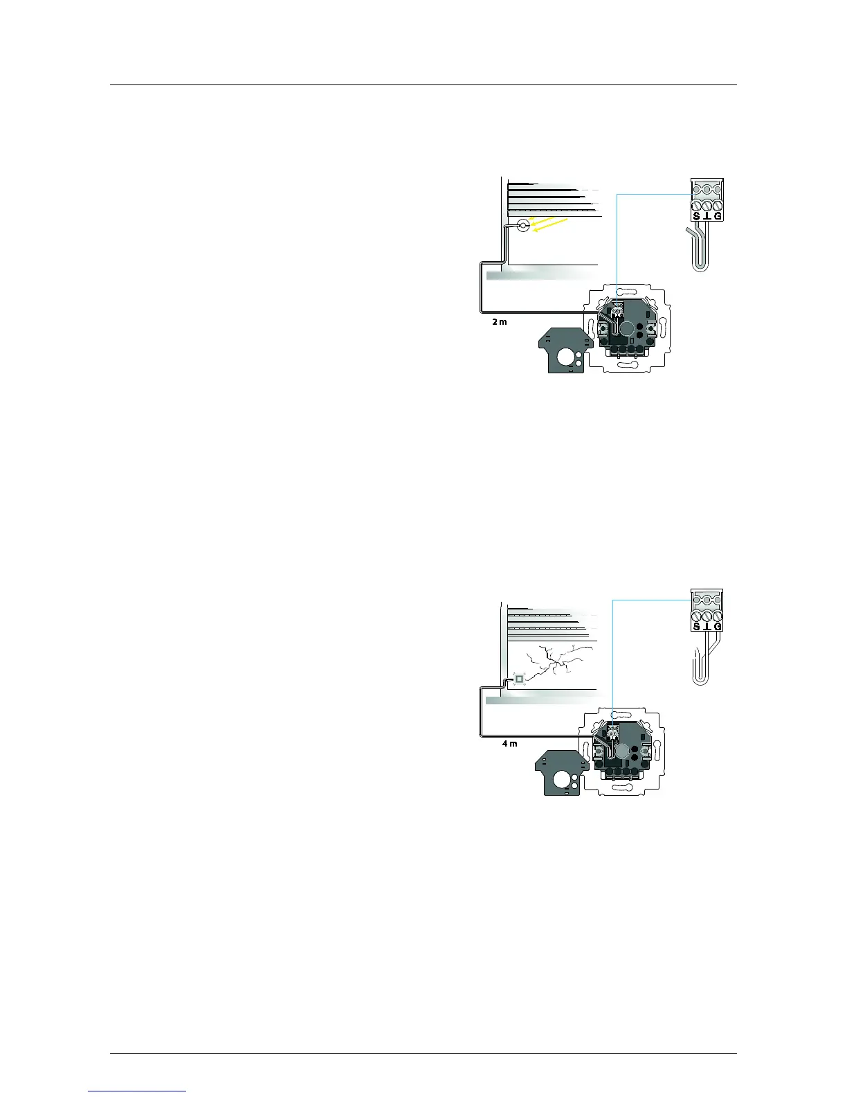
4.3 Brightness sensor
Pos: 22 / #Ne ustr ukt ur# /Onl in e-Do kume ntati on (+ KNX) /A ufba u u nd Fu nkti o n/Ti mer/ Hell ig keits se nsor - 64 55 J alo usie @ 28\mod_1347005872059_15.docx @ 232249 @ 312 @ 1
The connection of brightness sensors makes the automatic
closing of blinds possible as anti
sunlight or as protection for furnishings.
A brightness sensor can be attached directly to th
mounted insert with sensor connection, which is attached
to the pane with the aid of a suction cup. The values at
which a function is triggered can be set individually on the
flush
-mounted insert via a potentiometer and on the
element in the display, so that the
blind closes at the desired brightness.
If a set brightness is exceeded for a few minutes, the blind
travels down until it covers the sensor. The sensor is then
exposed again as the blind travels briefly up to measure
the current brightness.
If the running time is set so that the sensor cannot be
covered, the blind stops at the set running time. If the
brightness drops below the set value for several minutes,
the blind travels up again. This means that the function
rem
ains independent of whether the brightness sensor is
Fig. 1: Connected brightness sensor
The sensor can be attached at any position on the
window pane.
Pos: 23 / #Ne ustr ukt ur# /Onl in e-Dokumentation (+KNX)/Überschriften (--> Für all e D ok ument e <--) /2. E bene/ G - L/ Glas bruc h meld er @ 26\ mod_1343719382251_15.docx @ 226232 @ 2 @ 1
4.4 Glass break sensor
Pos: 24 / #Ne ustr ukt ur# /Onl in e-Dokumentation (+KNX)/Aufbau und Funktion/Timer/Glasbr uchm elder - 6 455 Jal ousie @ 26\ mod_1343719494192_15.docx @ 226245 @ 2222 @ 1
If the window pane is broken the blind is closed
immediately by the glass break sensor to prevent the living
area from sustaining damage.
The display of the comfort
trol element indicates the time when the damage
The blind can only be raised again manually onsite after
the alarm unit has been triggered. Commands via the
extension unit or automatic switching times of the timer
control element are ignored.
The glass break sensor is attached to the pane by means
of the enclosed double
-sided adhesive tape. For larger
glass areas up to four glass break sensors can be
combined on a single pane and connected to a flush
Fig. 2: Connected glass break sensor
Pos: 25 / #Ne ustr ukt ur# /Onl in e-Do kume ntati on (+ KNX) /S teuer mod ul e - Online-Dokumentation (--> Für alle Dokumente <--)/++++++++++++ Seitenumbruch ++++++++++++ @ 9\mod_1268898668093_0.docx @ 52149 @ 222 @ 1