8.4 Alarms
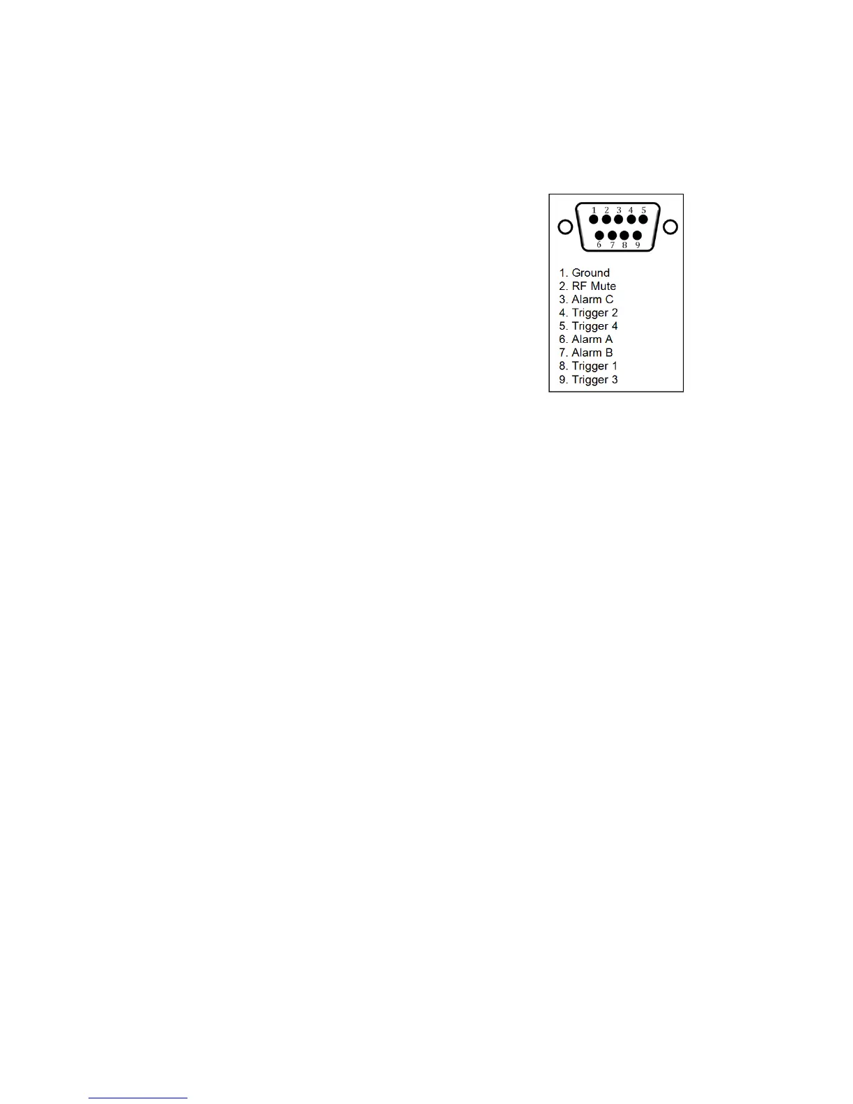
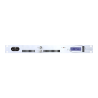
Figure 8.2: Alarms and Triggers Port
Alarms on the V2 Transmitter are used to indicate that
a failure condition is met. They can be set to trigger
on Modulation level, Forward power, Reverse power
and PLL lock fail. Upon triggering they will toggle the
relevant pin on the rear alarms and trigger connec-
tor. They will also write a notification to the RS232,
write to the system log and send an e-mail if required.
Alarm pins can be configured as open-collector Out-
puts (when working as alarms) or as Analogue out-
puts (for reporting system parameters as analogue
voltages). When used as alarms (open-collector out-
puts), 10 kOhm external pull-up resistors to 12 V should
be placed on each pin to be able observe voltage
changes in the alarm pins.
8.4.1 Type
Alarms can be configured as either alarms (open collector pins that will show ’0’ volts or open
collector depending on the result of the condition tested); or as analogue outputs, which will
report a parameter as an analogue voltage. The parameter Type allows this selection by pro-
viding the options Alarm and Analogue Out.
Alarms pins as Alarms
A Type
When the alarm Type is set to be Alarm, the system will look at the specified failure con-
dition in the Source parameter and trigger the alarm if the condition has been present
for longer than the specified On Delay time or release the alarm if the condition has not
been present for longer than the specified Off Delay time.
B Source
Selects the failure condition that alarm will watch for. Options are: Mod Level <, Mod
Level >, Fwd Power <, Fwd Power >, Rev Power <, Rev Power > and PLL Lock Fail.
- Mod Level observes conditions in the modulation (or deviation) level of the transmitted
signal.
- Fwd power observes conditions in the Forward power
- Rev power observes conditions in the Reverse power
- PLL Lock Fail observes if the PLL lock has failed and the system cannot tune to the re-
quired frequency.
67