26
Manual SOFTENER A27-A6X code P0011144 - Rev 3 - 09/02/2017
English
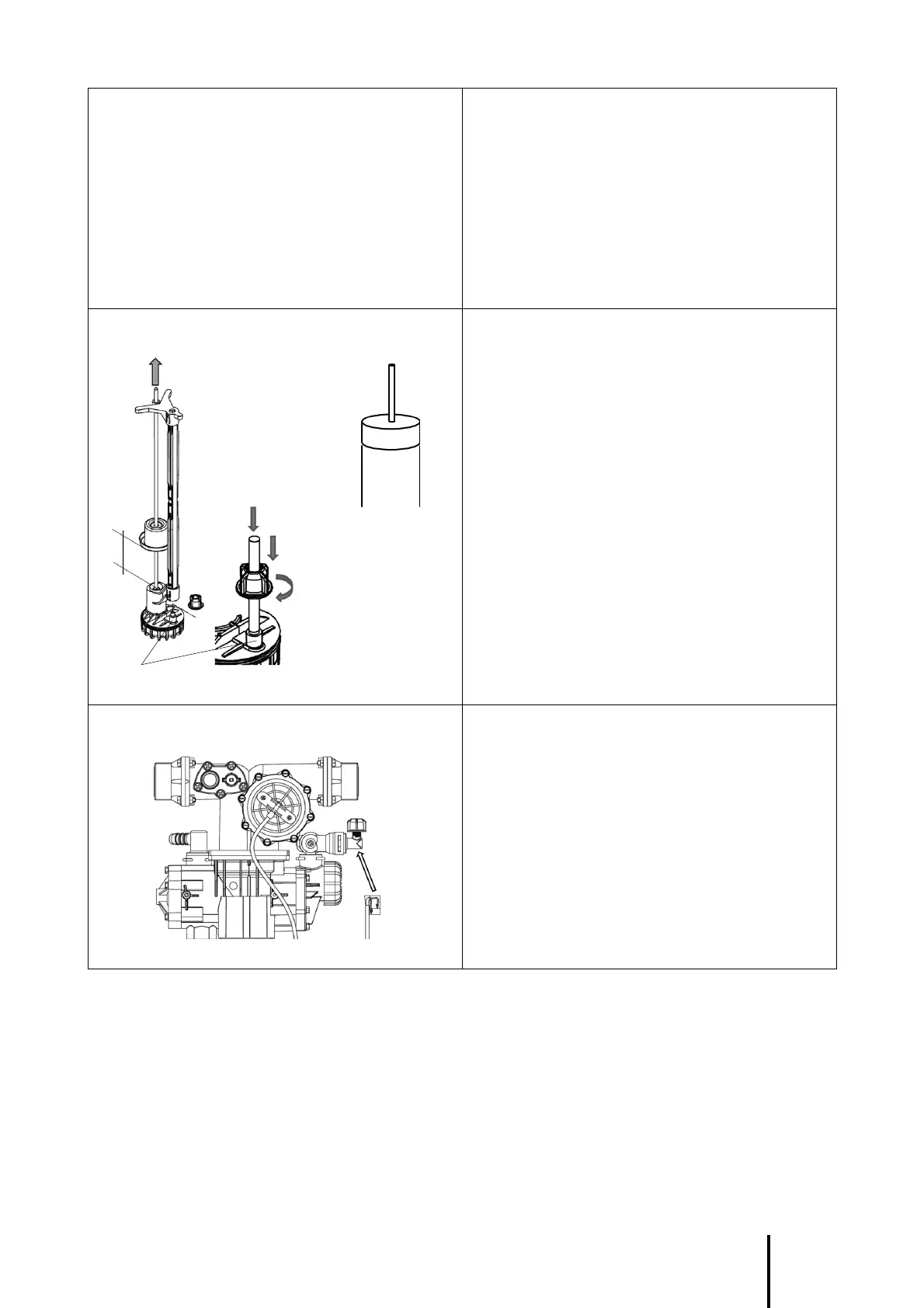
Connect drain outlets. Connect the drain tube (8) to the upper ! tting of
the siphon (11) and tighten it with a hose clamp
(Serfl ex type).
The siphon ensures the mandatory protection
of the domestic water circuit against sewage
backfl ow.
Connect the tube of the salt tank overfl ow (10)
to the side fi tting of the siphon (11), respecting a
slope of minimum 2% (2 cm per meter) from the
tank overfl ow to the siphon. Then tighten it with
a hose clamp (Serfl ex type).
The overfl ow must take benefi t of gravity and fol-
low a simple and short way. If not possible, install
a lift pump compatible with salted water.
Connect the siphon (11) to the drain by a rigid
PVC tube with a diameter of 40 mm, tightened
on the fi tting (25).
Complete the connections and purge the air. Before opening the water inlet into the installation,
purge and rinse properly the pipes upstream from
the bypass.
Connect the inlet and outlet fl exible hoses (13) to
the network pipe, by paying attention to the water
fl ow direction.
Progressively open the bypass tap (or the
upstream cutting valve of the installation).
Purge the remaining air by using the purging
screw upon the fi lter (unscrew it, then screw it
back once the air is purged).
Plug the softener to the electricity outlet.
8
25
10