6 HW Installation
6.1 Power-on Sequence
To power on the board, follow this procedure:
1. connect the 12V DC power supply to the DT5740 through the DC input rear connector;
2. power up the DT5740 through the ON/OFF rear switch.
See § 2.5 to identify the relevant components.
6.2 Power-on Status
At power-on, the module is in the following status:
the Output Buffer is cleared;
registers are set to their default configuration.
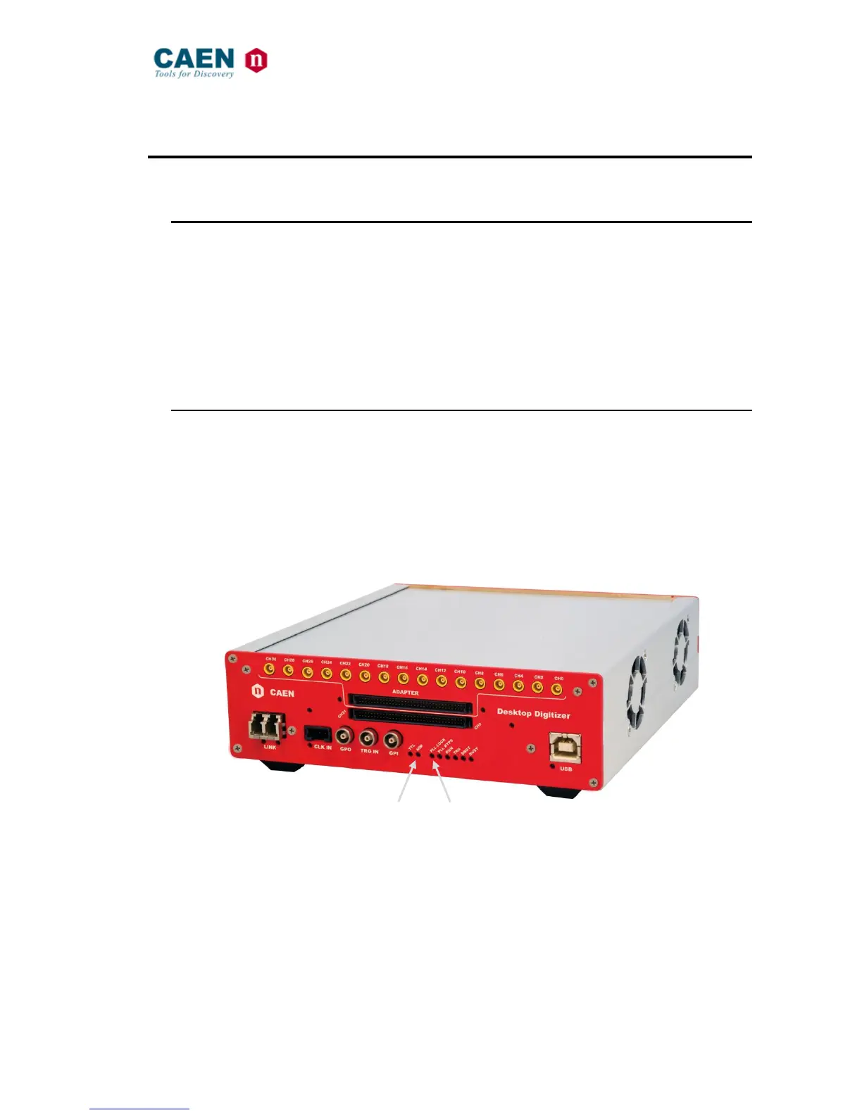
After the power-on, the front panel LEDs status is that only the NIM and PLL LOCK must light on.
Fig. 6.1: Front panel LEDs status at power-on